The shift to electric mobility has quietly but decisively changed the rules of shaft manufacturing. While internal combustion engine (ICE) shafts were designed around moderate rotational speeds and forgiving noise environments, electric vehicle (EV) rotor shafts operate in a radically different regime. Rotational speeds exceeding 18,000 RPM, instant torque delivery, and near-silent drivetrains mean that even microscopic form errors now translate directly into noise, vibration, and durability issues.
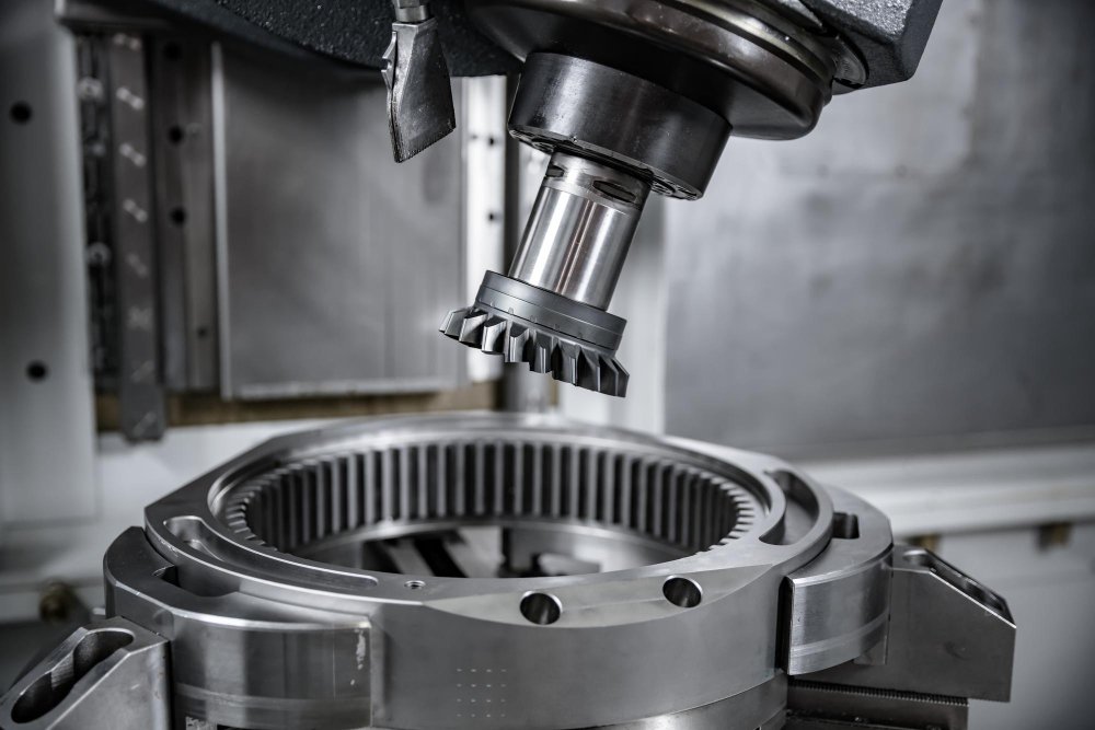
In this environment, grinding is no longer just a finishing operation; it is a functional enabler. Surface waviness, runout, taper, and residual stress patterns all influence NVH behaviour at high speed. Conventional 2-axis plunge grinding, while still effective for simpler geometries, struggles to deliver the consistency and cycle-time efficiency demanded by modern EV shafts. As a result, manufacturers are rapidly adopting multi-axis CNC grinding, typically with 3 to 5 controlled axes.
However, the true performance leap does not come from the machine configuration alone. The decisive factor is how intelligently the machine is programmed. Advanced CAM strategies, axis synchronisation, and data-driven compensation are what separate a capable multi-axis grinder from a truly production-ready EV shaft process.
Grinding EV Shafts at Micron Levels
EV rotor shafts are geometrically deceptive. At first glance, they appear to be simple, long, cylindrical components with bearing seats, seal journals, and spline interfaces. In practice, they are among the most challenging parts to grind accurately.
Their length-to-diameter ratio makes them inherently flexible, even when supported by centres and steady rests. Grinding forces that would be negligible on a short ICE shaft can cause measurable deflection in an EV shaft, leading to barrel shapes, taper, or lobing. At the same time, functional requirements have tightened dramatically. Runout values below 3 microns are increasingly common, and surface finishes in the Ra 0.1 µm range are no longer exceptional.
Compounding the challenge is the NVH sensitivity of EV drivetrains. Any discontinuity witness marks at shoulders, waviness at bearing seats, or imbalance due to uneven stock removal can excite high-frequency vibration modes that are immediately audible to the end user. Grinding strategies must therefore prioritise continuity of form and surface texture, not just size control.
The Role of Multi-Axis Grinding in Form Control
Multi-axis CNC grinding introduces an additional degree of freedom, fundamentally changing how material is removed. The most influential of these axes is the B-axis, which allows the grinding wheel to swivel relative to the workpiece. This capability transforms grinding from a sequence of discrete operations into a continuous, vector-controlled process.
In traditional 2-axis grinding, each feature diameter, shoulder, and radius is ground independently. The wheel approaches, plunges, retracts, and repositions. While accurate, this method almost inevitably introduces transition marks where features meet. At high rotational speeds, these transitions become stress concentrators and NVH triggers.
By contrast, a multi-axis approach allows the wheel orientation to change dynamically while remaining in contact with the part. When properly programmed, the grinding process becomes a single, flowing motion that preserves geometric continuity across the entire shaft.
B-Axis Vector Grinding: Eliminating Geometric Discontinuities
One of the most powerful programming strategies in multi-axis grinding is B-axis vector grinding. Instead of treating each feature as a separate entity, the CAM system calculates the instantaneous normal vector of the shaft profile and continuously aligns the wheel to that vector.
This has two critical benefits. First, it eliminates witness marks at transitions between diameters and shoulders. Second, it distributes grinding forces more evenly, reducing localised heat input and wheel wear.
In practice, this requires CAM software capable of true 5-axis interpolation rather than indexed positioning. The contact point between the wheel and the shaft must be recalculated continuously, and the CNC controller must synchronise linear and rotary axes with high precision. When executed correctly, the result is a surface that appears visually seamless and behaves mechanically as a single, continuous form.
For EV shafts, this continuity directly translates into lower excitation of bending modes at high speed, improving both noise behaviour and fatigue life.
Angular Wheel Engagement and Surface Functionalization
Beyond form accuracy, multi-axis grinding also enables surface engineering through the use of wheel orientation. By intentionally programming the B-axis to operate at non-traditional angles such as 15°, 22.5°, or even continuously varying angles, the programmer can control the directionality of grinding marks.
This is particularly valuable on bearing and seal seats. Linear plunge grinding tends to produce circumferential lay patterns that can promote lubricant migration or uneven wear. An angular approach, using the wheel periphery across both diameter and face, generates a subtle cross-hatched texture that improves oil retention and seal performance.
The key is consistency. The CAM strategy must ensure that the wheel orientation remains stable across the entire functional surface. Any abrupt angular change can introduce texture variation, which becomes a noise contributor at high speed.
Peel Grinding: Combining Accuracy with Throughput
One of the most effective strategies for reducing cycle time without sacrificing accuracy is peel grinding, also known as Schälschleifen. Rather than engaging the full wheel width in a plunge, peel grinding uses a narrow wheel to remove material in a helical path, much like a turning operation.
From a programming standpoint, peel grinding shifts the challenge from force management to synchronisation. The axial feed rate, wheel speed, and workpiece rotation must be precisely coordinated to maintain constant chip thickness. Any mismatch results in surface waviness or thermal instability.
Advanced CNC programs address this by using variable feed rate control. As the wheel approaches sensitive features such as shoulders, fillets, or spline roots, the feed is automatically reduced. Once the geometry stabilises, the feed ramps back up. This dynamic behaviour is impossible to manage manually and must be embedded directly into the CAM-generated toolpath.
When paired with CBN wheels, peel grinding allows high material removal rates while maintaining excellent surface integrity. For high-volume EV shaft production, it is often the single biggest contributor to cycle time reduction.
Constant Surface Speed: A Non-Negotiable Requirement
One of the most overlooked aspects of grinding programming is constant surface speed (CSS) control. As grinding wheels wear and are dressed, their effective diameter changes. Without CSS, this leads to variations in peripheral speed, directly affecting surface finish and thermal behaviour.
In EV shaft grinding, even a small drop in wheel speed can push a bearing seat out of specification during noise testing. Modern CNC programs, therefore, use real-time calculations to adjust spindle speed dynamically, ensuring the programmed surface speed remains constant regardless of wheel diameter.
This becomes especially critical in peel grinding, where chip thickness is tightly linked to surface speed. CSS is not an optimisation; it is a prerequisite for process stability.
Managing Deflection Through Intelligent Compensation
Mechanical solutions such as steady rests are essential for long shafts, but they are only half the solution. Without intelligent CNC logic, steady rests can introduce as many problems as they solve.
On advanced grinders, steady rests are often controlled as programmable axes. Rather than remaining static, they can move and adjust pressure dynamically as the wheel traverses the shaft. This follow-grinding approach ensures consistent support directly opposite the grinding force.
Pre-process probing adds another layer of control. By measuring the raw shaft’s runout before grinding, the CNC can shift the coordinate system to remove stock symmetrically. This prevents unbalanced mass distribution, a critical factor at 18,000 RPM and reduces the risk of post-grinding vibration issues.
Dressing Strategies: Preserving Form Over Time
In multi-axis grinding, wheel condition is inseparable from part accuracy. Complex shaft profiles place uneven loads on the wheel, leading to non-uniform wear. Traditional time- or part-count–based dressing strategies are inadequate in this context.
Instead, advanced programs use material-removal–based dressing logic. The CNC tracks the total volume of material removed and initiates dressing only when a defined threshold is reached. This ensures consistent wheel sharpness while minimising abrasive loss.
Acoustic emission (AE) sensors further refine the process. During dressing, AE signals allow the CNC to detect wheel–dresser contact within microns, eliminating air-dressing and ensuring precise truing. Over long production runs, this precision preserves form accuracy and stabilises cycle time.
Eliminating Non-Productive Time
In high-volume EV manufacturing, seconds per part accumulate into hours per shift. One of the most effective ways to reduce cycle time is to conduct an air-cut audit of the CNC program.
Excessive safety clearances, conservative approach speeds, and redundant positioning moves are common in legacy programs. Modern CNCs with look-ahead capability allow high-speed positioning until the wheel is within a millimetre of the part, switching to grinding feed only at the last moment.
Machines equipped with multiple wheel heads unlock even greater potential. By programming simultaneous operations such as grinding a main diameter with one wheel while finishing a spline with another, total cycle time can be reduced by up to 40%, without increasing risk.
Closed-Loop Manufacturing: Learning from Every Shaft
The final evolution in EV shaft grinding is data-driven compensation. Modern CNCs can receive feedback from post-process measurement systems such as CMMs or in-line gauging stations.
When measurement data indicates a consistent deviation, such as taper or lobing the CNC automatically updates compensation parameters in the grinding program. This closed-loop approach transforms grinding from a reactive process into a self-correcting system, ensuring long-term consistency even as tools, machines, and environmental conditions change.
Conclusion: Programming Is the Differentiator
Multi-axis CNC grinding has become a technical necessity for EV shaft manufacturing, but hardware alone is not enough. The real gains come from intelligent programming, from B-axis vector paths and peel grinding strategies to adaptive compensation and closed-loop control.
In the EV era, success is defined by the ability to grind complex shafts with micron-level accuracy at automotive production volumes. Achieving this requires moving beyond traditional plunge cycles and embracing CAM and CNC strategies that think, adapt, and learn.
In high-speed electric drivetrains, precision is no longer static; it is in motion.

Neha Basudkar Ghate
Techical Writer – Gear Technology India