Unlock Exclusive Access for FREE

Subscribe
Flash Story:

Key Basic Conditions in the Gear Shaving Process to Achieve Finish Gear Component Quality

Key Basic Conditions in the Gear Shaving Process to Achieve Finish Gear Component Quality

By: Ravi Naik

Material

Input Condition of CNC Blank:

  1. The material of the CNC blank with microstructure should be a well separated pearlite & ferrite; no banding is allowed.
  2. The CNC Blank Hardness must be 150-180BHN for better shaving quality and better shaving cutter life.
    If hardness is less, shaving cutter marks and cutter profile form errors even after a few shaving cycles takes place.
  3. Blank Face runout with respect to bore should be less than 25um The direct relation of blank face runout for controlling are: (a) Lead angular error (b) PCD runout.
  4. Face Parallelism should be less than 25um.
  5. Bore size, ovality and taper must be maintained as per specification.
  6. Parts should be free from loose hobbing burrs and metal chips in side flanks and complete parts. Otherwise, the loose burrs will stick between the cutter serrations and material removal will not be effective.
  7. Span size stock must not be more than 30-50um. In OPD, it must be between 70-90m maximum, and one must refer to the hob drawing. Similarly, also for span size / OPD, the size must be mentioned in the hob drawing.
  8. Shaving stock per flank should be as per the protuberance amount provided on shaving cutter.
    Hobbed gear with undercut to avoid the fouling of the cutter with material allowance of maximum 25 microns/flank for shaving operation.
  9. Profile angular error (Fha) in hobbing to be maintained similar as per Fha value required in shaving to ensure uniform cutting load.
    Example: if Fha require +1 to +5 in shaving then maintain +1 to + 5 in hobbing.
  10. For input shaving operation, hobbed gears must be with tip chamfer to avoid dents.

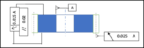
Fig 1: Face runout , Face // & Gear PCD Runout
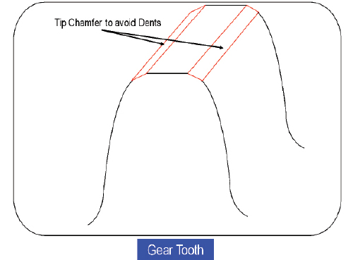
Fig 2: Semi Topping

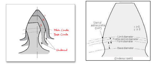
Fig 3: Protuberance pictorial view

Shaving Fixture

  1. Collet clamping or hydraulic expansion fixtures for zero clearance between part bore and clamping fixture.
    This take cares of controlling PCD runout , Fh-alpa variation and span size variation.
  2. Part slippage in fixture needs to be checked during setup, and the clamping force be set accordingly.
  3. Part slippage torque should be checked in every shift.
  4. Tailstock clamping force need to be fixed as per part configuration.
  5. For collet clamping mandrel, collet life to be monitored and replaced as per decided frequency.
  6. If mandrel is hydraulic, mandrel OD size to be checked and replaced after wear limit. Don’t forget to check part clamping; if clamping is not firm, fill the oil as per standard operation procedures to ensure part
    clamping.
  7. Mandrel resting plate and clamping cap runout need to check every day and maintained as this will take care of lead errors.
  8. Runout master component must be checked during setup, and at set frequency.
  9. Fixture resting face, tailstock clamping cap, and collet must be cleaned every shift.

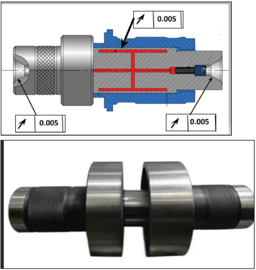
Fig 4: Hydraulic mandrel

Tool Shaving Cutter

  1. Shaving cutter with material ASP2023 or higher grade to be used.
  2. Shaving cutter with standard bore size 63.50 mm
    (2 ½”) to be used.
  3. Shaving cutter profile needs to maintain as per part profile requirement after shaving considering heat treatment distortion pattern.
  4. Maintain the cutter profile and crowning as per established profile angular and profile crowning, and lead crowning. If part profile angular error (Fh-alpa) is required to be negative, then the cutter profile angular also needs to maintained in negative only. This again depends on the process cutting parameters (RPM, number of passes, and feed).
    In every cutter sharpening, the established profile angular (Fh- alpa) and crowning needs to maintained. This will control Fh- alpa and profile crowning on part.
  5. In shaving cutter sharpening, the stock removal in resharpening should not be more than 0.03-0.05mm, and it should follow ROP ROD Chart for Cutter for OD grinding correctly.
  6. If cutter is the plunge type, and lead crowning is required, then calculate the crowning required on cutter to obtain crowning on part.
  7. Shaving cutter should be demagnetized, and washed every time after removing the cutter from the machine.
  8. The cutter should be handled carefully, and kept in a box provided by the tool supplier after every use.
  9. 9. The cutter face should be free from dents and damages. Check for flatness of cutter as per frequency.

Method

Cutter RPM, feed, number passes and dwell time need to be established as per the gear profile angular error and profile crowning required on part.

Types of Shaving:

  • Plunge shaving is used for lower cycle time, and if the lead crowning part is required, then the cutter should have lead crowning.
  • Diagonal Shaving: If part crowning is higher and part width is higher than cutter width, then diagonal shaving is preferred.
  • Diagonal shaving cycle time is higher compared to Plunge shaving. For diagonal shaving, suitable cutter is needed to be designed and manufactured.

D-Machine

  1. Machine conditions –
    -Cutter Spindle Runout must be checked and ensure within 0.01mm or as per GA Test chart.
    -Alignments of head stock and Tailstock need to maintained within 0.01mm or as per GA test chart.
  2. Machine leveling should be ensured, else it leads to profile form error.
  3. In conventional shaving, the machine table axis repeatability must be checked. This leads to span size variation.
  4. For chip flushing, cutting oil flow rate and direction of flow need to maintained.
  5. Machine JH condition monitoring and actions need to be followed for machine basic health condition.
  6. Follow the preventive maintenance schedule and critical spare parts planning.

Conclusion

Part shaving quality effects final part quality; therefore, the shaving process basic conditions must be maintained to achieve required finish gear quality.