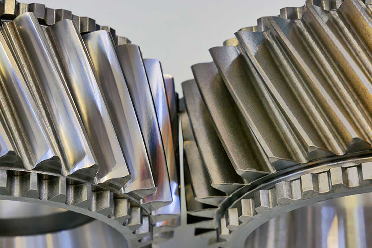
Gears after polishing (left) and after shot peening (right)
The electric motors used in e-mobility have a significantly higher efficiency compared to conventional combustion engines: Up to 80 percent of the energy stored in the battery is transferred to the wheels as kinetic energy by the highly efficient electric motors by means of a transmission. When burning fossil fuels, the yield of 30 to 40 percent is only about half.
Nevertheless, efforts are underway to further increase the energy efficiency of electric cars, especially regarding the achievable ranges. A key element is also the surface texture of the gear flanks in the transmissions used.
The process which determines the quality is the hard finishing of gears through grinding and subsequent superfinishing at the end of the gear processing chain. There are constantly increasing demands on service life, smooth running, power transmission and efficient use of the introduced energy.
Since there is no official definition for the terms of fine grinding and polishing, KAPP NILES has created a definition that refers to the achievable surface quality during generating grinding (Table 1).
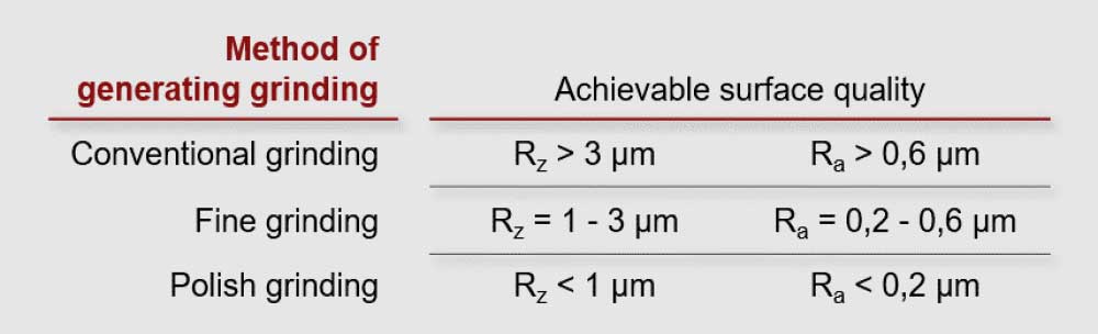
The average roughness depth Rz and the average roughness height Ra were used as comparative values. However, it is understood that from certain surface qualities onwards, other values such as material ratios are better for characterizing the surface than Rz and Ra.
In order to meet the increasing surface requirements, various tools are also used in the different processes, as described below.
In standard generating grinding, a vitrified bonded corundum grinding worm is used, which consists entirely of one specification.
In the multi-stage, combined machining process of superfinishing, a different grinding worm specification is used for rough grinding (conventional generating grinding) than in the actual fine grinding. Both specifications include a vitrified bonding but may have different types of corundum and/or grain sizes.
In the multi-stage, combined machining process of polishing, a grinding worm with vitrified bonding is used for rough grinding (conventional generating grinding) and a grinding worm with a polyurethane or synthetic resin bonding for polishing.
In a one-step machining process of polishing (not in combination with direct rough grinding), a one-piece tool with polyurethane or synthetic resin bonding is used.
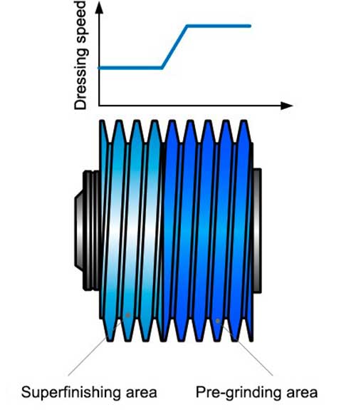
Fig 1: Reduction of dressing speed
The tool consists of two different tool specifications. In the area used for fine grinding, the feed speed is reduced during dressing (Figure 1). This makes it possible to influence the achievable surface quality of the workpiece. This procedure for dressing influences the surface quality of the gear wheel, even if the grinding worm consists of only a single specification.
In the following images, profile and flank line measurements are each shown before and after fine grinding. It is already apparent in the profile measurement log of the gearing measurement (Figure 3) that the profile shape deviation (ffα) could be significantly improved with this grinding / dressing technique.
As expected, there was no change in the lead measurement (Figure 5), as the grinding grooves are in the direction of the tooth width in accordance with the largest velocity vector.
From the graphical comparison of the roughness measurement (Figure 6_7), it can be seen that the surface has been smoothed. However, a roughness structure can still be seen. That is to say, the average roughness depth Rz and the average roughness height Ra could be reduced by a factor of 2 to 3. The core roughness depth Rk and the reduced center height Rpk could be reduced by a factor of 2 (see Table 2).
Another area of application for high-precision machined gear flank surfaces are truck transmissions for both electric drives and conventional drivetrains. Nowadays, electric lorries are used in areas such as waste management or for the delivery of consumer goods in cities. Some food discounters even advertise that the transport of their goods between their stores in big cities is carried out with electrically powered trucks.
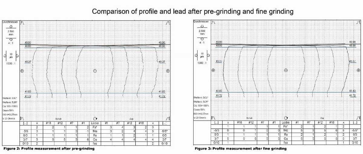
Fig 2: Profile measurement after pre-grinding & Fig 3: Profile measurement after fine grinding
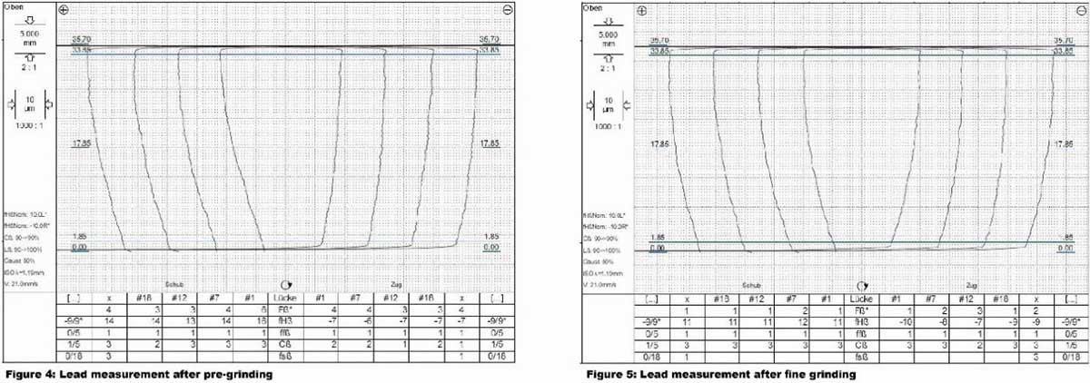
Fig 4: Lead measurement after pre-grinding & Fig 5: Lead measurement after fine grinding
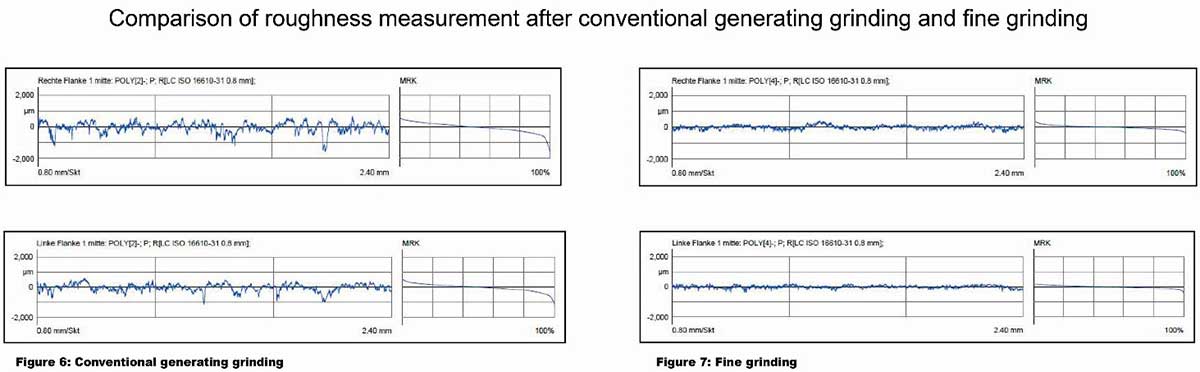
Figure 6: Conventional generating grinding & Fig 7: Fine grinding
The polish grinding of shot-peened gear flanks is presented below.
The work sequence is as follows: After hardening, gears are machined as usual with the generating grinding process, using a one-piece grinding worm. As a result, the existing grinding stock including heat distortions is eliminated and the final workpiece geometry is produced.
Afterwards, the gear flanks of the workpieces are shot-peened. The reason for shot-peening is the hardening of the gear flank surface, which serves to extend the service life of the gears and therefore the transmission. In the last step, the gear flanks are polished on a generating grinding machine with a one-piece polyurethane bonded tool.
By polishing, microscopic raised areas caused by shot-peening can be eliminated. It is not necessary to eliminate all indentations.
Two gears were compared in Figure 8. On the left, the workpiece is shown after shot- blasting and on the right, the workpiece is shown after polish grinding of the gear flanks.
The following two Figures 9 and 10 show the basic comparison of the profile geometry. In Figure 10, the reduction of the corrugation by polishing is clearly visible. The basic geometry of the profile is not affected. The profile angle deviation fHα, the profile convexity Cα and the tip relief Cαa are generated during conventional generating grinding processing prior to shot-peening.
Figures 11 and 12 show the comparison of the flank line geometry. The measurement log of the lead measurement after shot-peening is shown in Figure 11. Here, the lead shape deviations ffβ at approx. 7 μm are clearly visible. Figure 12 shows another workpiece of the series being machined, here the lead measurement after polishing.
The basic geometry of the flank line is not affected. The lead angle deviation fHβ and the lead convexity Cβ are generated during conventional generating grinding processing prior to shot-peening. As documented in Figure 12, the lead shape deviation ffβ is reduced by half.
As a final evaluation criterion, a comparison of the surface quality (Figure 13_14) is now carried out. After shot-peening, the average roughness height value Ra is significantly above the usually required qualities at ~0.85 μm. Likewise, at ~5.8 μm, the Rz is too large for the required application.
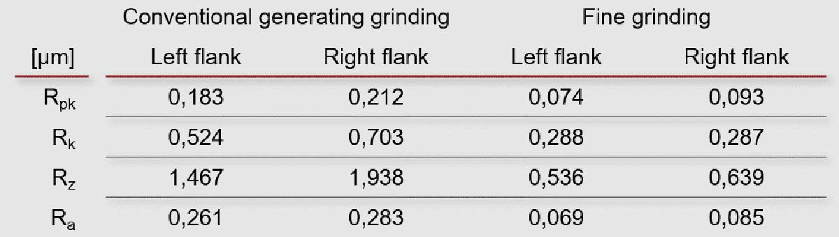
Table 2: Comparison of surface characteristics
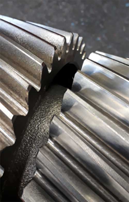
Fig 8: Comparison of two workpieces
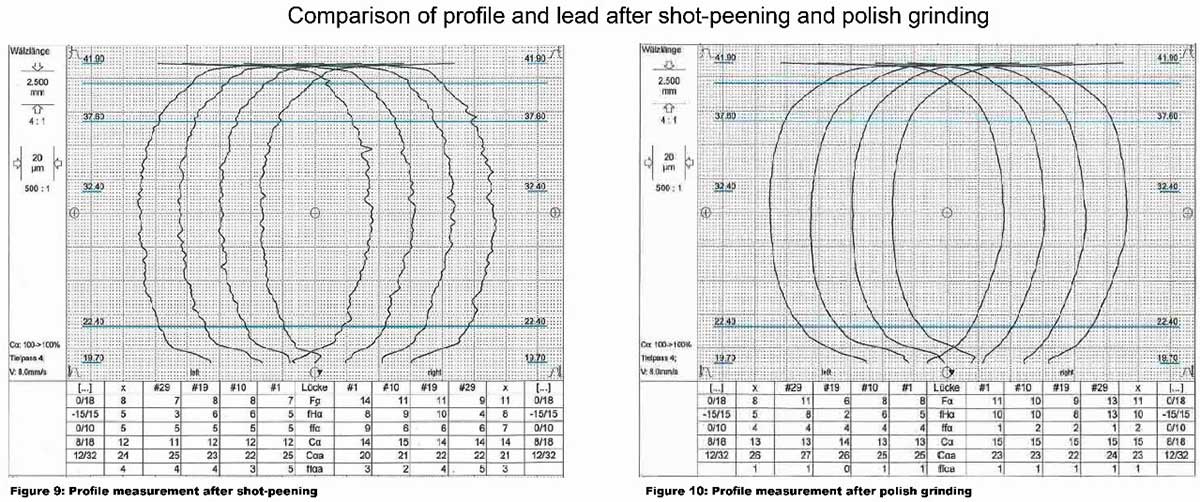
Fig 9: Profile measurement after shot-peening & Fig 10: Profile measurement after polish grinding
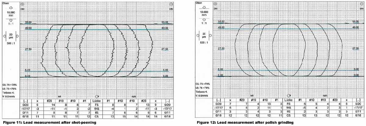
Fig 11: Lead measurement after shot-peening & Fig 12: Lead measurement after polish grinding
After polishing, the characteristic values Ra and Rz show very small values. These are no longer meaningful enough in the description of the surface quality. Rather, material yield fraction Rmr or the “reduced peak value” Rpk together with the core roughness value Rk come into play here. In this context, there are a wide range of evaluations to describe the achieved surface quality.
In summary, the following advantages are combined with the production sequence shown here:
Geometric accuracy through conventional generating grinding
Surface compaction through shot-peening
High-precision surfaces through polishing
This work chain contributes to increasing the efficiency and service life of the transmissions of today and tomorrow.
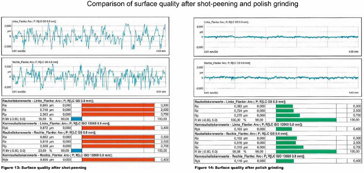
Fig 13: Surface quality after shot peening & Figure 14: Surface quality after polish grinding
 The author is Patrick Duhre, Manager for Contracting and Test Grinding.

The author is José López, Head of technology and tool development.