Introduction:-
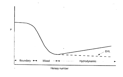
Typical Stribeck Curve represents basically different regimes of lubricated conditions. Consequently, the Hersey number on the abscissa can imply the Lubricant film thickness to show a higher Hersey number representing a thick film. This enables to find different Stribeck Curves in literature carrying a variety of parameters on the abscissa such as rolling speed of gear, entertainment speed, film thickness and similar parameters which can alter the value of friction.
A smaller Hersey number can represent a boundary lubrication and a coefficient of friction at a higher value. When the number increases, there is a rapid decrease in friction coefficient. This is accompanied by a transition from boundary conditions to mixed lubrication and hydrodynamic regime. Hence, friction is a quantity that keeps changing at different tooth contact conditions in the process of lubricants that separate the contacting flanks under load.
In this paper we will see how as to how the friction coefficient changes at different regimes of lubrication; how the film thickness is addressed under partial EHL (Elastohydrodynamic Lubrication) and under transition. Besides, various methods adapted to evaluate the friction coefficient under shear of lube oil film by load and how various researches have considered when calculating load-dependent power loss.
1. The Friction Model
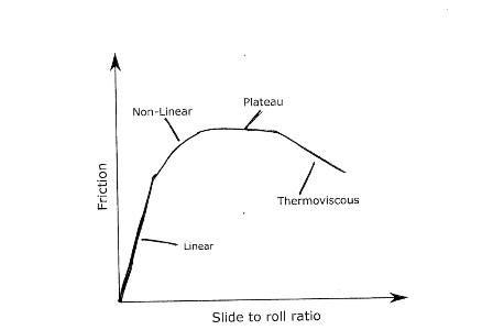
The Friction Model accounts for the non-Newtonian shear thinning behaviour of lubricant film. Further progression of dealing with this phenomenon leads to thermal behaviour or effect which enables prediction of lubricant temperature due to inlet oil shear heating. For a move out let us limit to the regime before the rise of temp/ pressure for the friction effect to remain in the scope.
The generated EHD pressure profile closely follows the Hertzian pressure profile under the entrainment except for inlet trail and secondary pressure peak in the contact outlet. This friction model has the basis deviating from the need for full solution of Reynolds fluid flow under the assumption of medium to high loads rendering piezo viscous Elastic EHD.
The central region carries the film shape as nearly flat at the height of the central film thickness. Depending on the form and slope errors and flank form conditions on the basis of load deflection, the contact zone can alter the film thickness. The contact area contour among meshing tooth flanks and deflection passed on by the load under transmission the film thickness alter. This gets subject to load-based shear caused on to the layer of oil film close to the driving flank pressing on the driven side flank by the layer of the oil film near that flank.
The friction under this scenario can be under for a given lub oil:
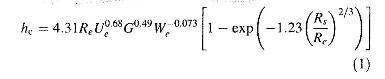
Where
Ue – Dowson speed parameter – relative to entraining speed
Re – effective Radius of Curvature along the entraining direction (say X-axis)
G Dowson parameter
We Dowson Load Parameter
Rs Effective Radius of Curvature transverse to Re
Entraining speed Ue for oil flow inlet depends on dynamic viscosity at inlet, limit inlet temp and reduced elasticity modulus.
For simpler use and application where the pressure gradient of oil can be neglected as is assumed commonly in analytical EHD solution the shear rate is:-
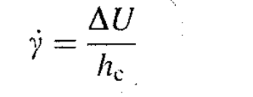
t is the shear stress
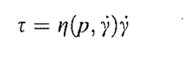
η is the effective dynamic viscosity.
Which is an important basic phenomenon
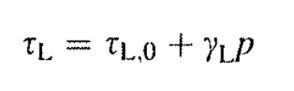
γL is the limiting shear stress pressure-based coefficient
P – Contact Pressure based on load
tL – Limiting Shear Stress
The friction coefficient:
μ = t/ p
where t is the average shear stress under EHD contact in pascals and p is the mean contact Hertzian pressure.
STAY TUNED TO READ THE NEXT PART IN THE UPCOMING EDITION!