This article is based on the pioneering research and development conducted by the Design Unit at the University of Newcastle upon Tyne, home to the UK’s National Gear Metrology Laboratory. The primary research was spearheaded by J. Hu and R.C. Frazer, experts in analytical gear measurement, alongside J.A. Pennell. Their work has been instrumental in transitioning worm gear inspection from subjective contact marking to absolute, traceable CNC standards.
For decades, the production of involute worm gears has been a cornerstone of the power transmission industry. Yet, while manufacturers of spur and helical gears have long enjoyed standardised analytical inspection, worm gear producers have traditionally relied on “contact marking”—a process that often feels more like an art than a science.
As precision requirements tighten, moving from “matching a pattern” to “measuring a geometry” is no longer a luxury; it is a necessity for the future of gear technology.
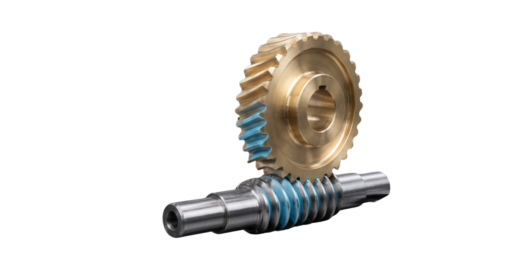
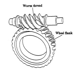
While the involute worm itself is essentially an accurate screw thread and relatively simple to measure, the mating worm wheel presents a far more complex geometric challenge. Unlike parallel-axis gears, a mechanical inspection machine for worm wheels was historically considered unfeasible due to the intricate, non-linear nature of the tooth flank.
Worm wheel manufacturers have traditionally used a contact marking test procedure:
This process is repeatable but lacks diagnostic power. It cannot identify whether an error stems from the profile, pitch, or lead, making it nearly impossible to determine the true source of manufacturing deviations.
Developed at the University of Newcastle upon Tyne and validated at the UK’s National Gear Metrology Laboratory, a new procedure allows for the absolute measurement of worm wheels. Unlike comparative measurements that merely check a part against a “master,” this method inspects the wheel against its theoretical tooth form.
1. Defining the Mathematical Model
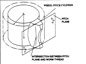
Before measurement begins, a kinematic model generates the theoretical tooth surface. This model effectively simulates the manufacturing process, replacing the cutting tool geometry with the mating worm’s geometry.
2. Simplified Inspection Strategy
The Mathematical Foundation of the Lead Curve
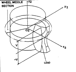
The core innovation of this absolute measurement method lies in how the software derives the theoretical tooth form. Unlike parallel-axis gears, the lead of a worm wheel is not a simple helix; it is defined by two primary factors:
By defining this spatial trajectory, the CNC probe can move simultaneously across linear and rotary axes to measure the resulting curve with absolute precision.
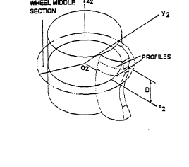
Measuring the total topography of the tooth would be too time-consuming. Instead, the procedure focuses on two critical areas:
The reliability of this CNC procedure is backed by rigorous validation using a standard 4-axis machine, such as the Gleason GMS 430.
While the mathematical model provides the theoretical path, physical mechanics introduces challenges during the measurement of large-diameter wheels.
The true value of analytical data is demonstrated in troubleshooting. A passenger lift drive exhibited excessive noise and vibration. While traditional marking might show a poor pattern, the CNC inspection revealed large profile errors.
The data identified this as a tooling error (a faulty hob) rather than a design flaw. After the hob was re-ground and a new wheel manufactured, profile and lead errors were significantly reduced, and the lift operated within acceptable noise levels. This type of precision diagnosis is impossible with contact marking alone. (Hu et al., 1997).
Analytical measurement allows manufacturers to finally quantify the accuracy of worm wheels. By eliminating the confusion caused by previously unquantifiable errors, shops can optimise process capability, verify accuracy traceably, and significantly reduce the time spent on manual “trial and error” adjustments.
Aroop Kumar Sen
Project and Sales Manager
TASA Automotive Components