Last Tooth Error (LTE) is a distinctive surface imperfection encountered in the gear shaping process, particularly in helical gears. It manifests as a linear mark on the tooth flank at the completion of the finish rotary pass. Although subtle, LTE can significantly affect gear quality perception and, in some cases, functional performance. This article explains the nature of Last Tooth Error, differentiates it from sudden variations, discusses its probable causes, and outlines best practices for detection and prevention.
Gear shaping is a highly synchronised generating process in which the cutter and workpiece rotate in a precisely timed relationship. Any transient disturbance in this synchronisation—especially at the completion of a rotary cycle—can leave behind a visible signature on the gear tooth flank. One such signature is known as Last Tooth Error (LTE).
LTE is often overlooked because it may not consistently appear in conventional inspection graphs. However, with increasing helix angles and higher machine dynamics, its occurrence has become more noticeable and relevant to both manufacturing engineers and quality professionals.
Last Tooth Error is identified as a straight vertical line on the tooth flank, running parallel to the gear axis. The mark typically appears at the end of the finish rotary pass, corresponding to 360° rotation of the workpiece. It may appear on a single tooth flank or multiple adjoining flanks.
Salient features include:
The term “Last Tooth Error” originates from its consistent occurrence at the angular position corresponding to the completion of one full rotary cycle of the workpiece.
Unlike classical profile or lead errors, LTE does not necessarily appear at the pitch circle diameter or reference diameter. Its position may shift toward the tooth face or flank, and its length may not extend across the entire face width.
As a result:
The visibility and severity of LTE increase with increasing helix angle, owing to the higher degree of axial and radial synchronisation involved.
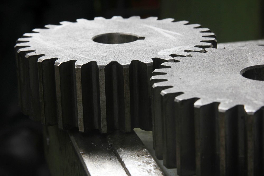
LTE can occur in both spur and helical gears. In spur gears, the vertical nature of the mark causes it to merge with feed marks, making it narrower and less conspicuous. Consequently, LTE in spur gears is rarely detected through measurement or visual inspection. In contrast, helical gears exhibit clearer and wider LTE marks due to their geometry and motion characteristics.
Last Tooth Error is sometimes mistaken for sudden variation. While both may appear as localised deviations on the tooth surface, their origin and behaviour differ fundamentally.
Although LTE may be interpreted as a form of sudden variation, not all sudden variations can be classified as Last Tooth Error.
The occurrence of LTE is primarily associated with synchronisation disturbances and mechanical or control-related instabilities at the end of the generating cycle.
The sporadic nature of some of these factors explains why LTE may appear on only a few components within a production batch.
One of the defining challenges of Last Tooth Error is its inconsistent detectability through standard inspection methods. Reliable identification requires:
Ballpoint measurement alone is insufficient for confirming LTE.
To minimise the occurrence of Last Tooth Error, special attention must be given to machine synchronisation during testing and setup, particularly when using electronic gear linking systems.
Recommended practices include: –
In addition, ensuring mechanical rigidity, eliminating backlash, providing adequate back-off, and setting correct cutter offsets are essential preventive measures.
Last Tooth Error is a subtle yet distinct manifestation of synchronisation imperfection in the gear shaping process. While it may not always influence functional performance, its presence reflects the dynamic behaviour of the machine–process system, particularly after the generating cycle.
With increasing demands on gear quality and higher helix angles, understanding and controlling LTE has become increasingly important. Through disciplined machine synchronisation, robust mechanical integrity, and thoughtful process setup, Last Tooth Error can be effectively minimised or eliminated.
Vishwajit Rajkumar Kothari, Director Cyber Gear
Vishwajit Rajkumar Kothari is a highly experienced professional in gear manufacturing and CNC machine tools, with over three decades of hands-on industry exposure. His work spans technical sales, application engineering, CNC programming, tooling and fixture development, and machine commissioning. He has led turnkey projects for leading automotive and defence customers and has gained international experience through training and commissioning assignments in Germany and Italy.