
In a systematic calculation for load capacity against bending stress in cylindrical gears, all predictable factors were considered in gear design to foresee corrective steps or a corrected tooth form to accomplish.
There were some parameters which were applied for simplification.
i) The gearing and load distribution across face width were assumed uniform, and the tooth form for helical gears was adapted to a similar spur tooth with a virtual number of teeth and a critical section for bending was set at the tooth root at 30° tangent to the fillet.
ii) Working procedures were evaluated and endurance limits established for the material chosen, compared and applied. These procedures were improved by superimposing work experience and test results to alter the bending strength value estimated to optimise the deflection value.
These were practised by various well-known gear manufacturers such as Maag, Switzerland, who pioneered to optimise the calculations to update to better with the ISO.
With the development of computer science technology, the FEM could be used to work swiftly and be applied. Here boundary conditions were to be defined with a degree of discretisation.
Body-induced deflection is a part of various load-based deformations, which include bending, shear, compression and coupling stresses int two-tooth contact region and the single tooth contact region. This resultant value, as a sum of components together with the contact stress-based deformation account for the mesh stiffness.
Over a period of time, it has been a practice to first address the contact stress and evaluate contact fatigue limits using the involved factors.
The intensity of Hertzian pressure induced on the tooth flank varies with shape and geometry, and is mostly non-linear. The effective radius of curvature between the meshing flanks takes the instantaneous value.
As mentioned in the previous paragraph, the local body-induced deflection has to be ascertained considering the sources in the gear geometry and solid structure. It is often referred to as fillet foundation stiffness, also as the reciprocal of deflection measured along the deflection angle at the root circle. The base radius deflection angle and the root circle-based arc shift calculations exist.
The basic analytical approach to find the gear body deformation or deflection is considering the potential energy, in which the energies stored in each of the constituents under deformation act as a sum.
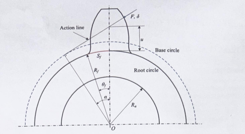
Figure 1. An elastic tooth subjected to a force F.
The said deflection is fixed analytically as follows:
Equation 1
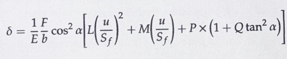
The parameters are the load, Young’s modulus E, face width of the gear, pressure angle, a quantity u representing the distance between the root circle and the point of intersection of the tooth center line at the meshing zone. This intersection can be through the pitch point relative to the mesh position and the force applied near the tip of the tooth in the mesh, which causes the body-induced deflection.
The coefficients L, M, P and Q are determined to get the estimated value of deflection. This equation is used widely, yet the accuracy can change based on single tooth contact and two-tooth contact zone in a mesh cycle.
In an attempt to calculate mesh stiffness, researchers such as Kissling, Mahr and those from the University in Madrid, Spain applied methods to find bending, shear and compressive stiffness in the form of analytical formulae.
Weber and Banaschek found equations for gear body-induced stiffness as well as contact stiffness. Due to the limitations on the contact stiffness, along the line of action calculations with planar deformation theory remain partially used.
Besides the assumption by Banaschek for the tooth center line remaining rigid and the applied tip load to cause body induced deflection, and the angle shift through theta value applies Beltrami identified partial portions only of this hypothesis has been used in known gear design software.
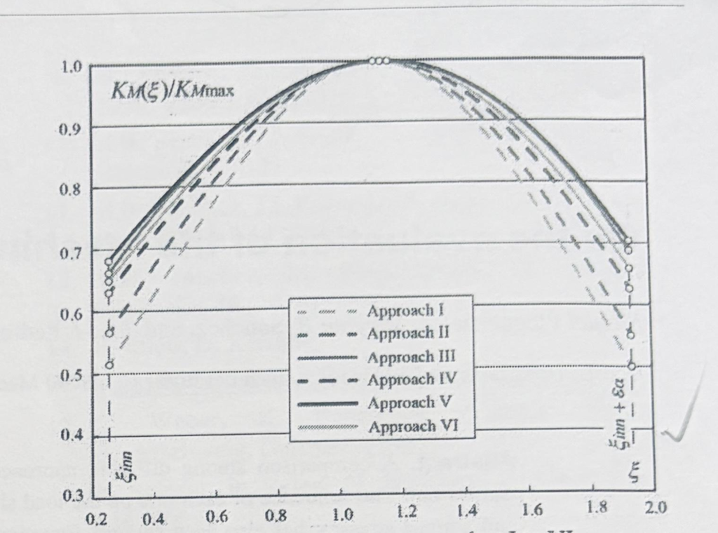
Fig. 2 curves of MS according to approaches)
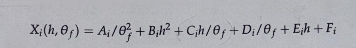
Equation-2
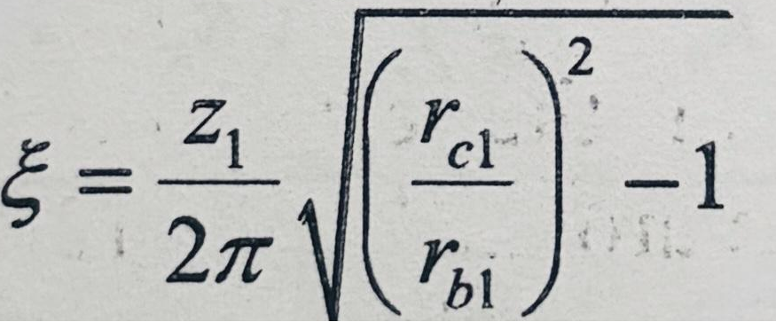
The mesh stiffness computation can be done as a function of a contact point parameter ξ, which is a meshing position along the path of contact as:
Equation 3

The contact load deformation on the line of action on the profile is the least at the centre of the path of contact and close to the pitch circle. The mesh stiffness at the point is maximum by analytical means of display or FE simulation.
Modified form of equation in 1 is necessary on the basis of the following considerations:
i) To enable the inclusion of the two teeth contact phase in the mesh cycle in addition to single tooth contact.
ii) For the above, a coupling stress deformation is necessary to link all the bending-related deformations for better accuracy for the total value.
iii) Values for body deformation theta and a practical ratio for quantities responsible for the variation in its magnitude are to be calculated.
This ratio defines the root dia and the gear hub rim thickness. This quantity takes the gear bore diameter where applicable, instead of the hub diameter.
Consequently, the following equation applies to improve equation 1.
Equation 4
The use of the coupling effect between adjacent engaging teeth and changes in root stress as parabolic as well as cubic to reach an improved solution has come in a few years ago. The stage has arrived with an involved calculation of coupling stress for overall stress level assessment. This has also led to finding a corresponding deformation of total value in knowing the change in transmission error in the presence of lubricated tooth flanks. This branches out separately to a different analysis involving thermo-EHL lubrication regime.
Through an assumption and setting the model of the gear body either fully elastic or a portion below the root, there is a possibility to find the deformation induced by the gear body under load.
i) In a prediction where the gear as a total unit as elastic is set, and the load applied at the strategic tip end, and the deflection delta is measured along the line of action, both body-induced deflection and tooth deformation can be seen as total deflection.
Thereafter, fixing the gear body in rigid mode and applying the load on the tip of the tooth at the same location, the resulting deflection delta measured along the line of action becomes the tooth elastic deflection. The difference between the two gives the body induced deflection.
ii) The alternate way is to find the force on the root generated by an applied load at the tip. 0The corresponding forces at the root side in reduced values cause tooth deflection along the path of contact, which is the body-induced deformation directly.
Both methods can give the desired results.
Plane strain model applied to 2D on FEA plane 183 was used to verify the effect of body-induced deflection by evaluating the body stiffness on ordinate versus the angular displacement on the root dia on the abscissa.
This method assessed body stiffness per unit facewidth.
The force at the tip was applied on one tooth, and the effect on the deformation of body deflection angle calculated for five sets of facewidths, keeping the pitch diameter of the gear and bore diameter the same. In other words, the rim thickness remained the same.
The report on the stiffness value showed that the error on facewidths of chosen gears of 20 mm, 30 mm, 40 mm and 50 mm was negligible. When the face width narrows down, the error shows about 10%.
It is true that the module in this exercise shows less or no significant effect on body-induced deflection or the stiffness per unit facewidth for the tested gears of spur type.
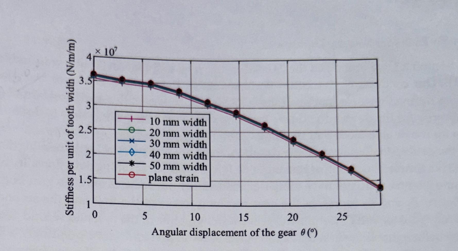
Fig. 3 Comparison between 2-D and 3-D models
A comparison between the analytical methods mentioned and optimising the coefficients of these equations for improved results, and the Finite Element analysis-based plane strain model was made. This was done using the adjustment of coefficient values of analytical equations, and inferred as a deviation of up to 20% occurs in the previously reported analytical method that uses the ratio of root circle radius to bore radius or hub radius.
The variables such as the number of teeth, the ratio of root circle to bore radius and relative comparison error were applied.
The analytical models used for determining the load-induced deflections other than contact stress-based/Hertzian pressure are very useful in knowing the body-induced deflection. This used to be integral in the assessment of bending load deformation, earlier to FEM methods or 2D analytical models.
The single tooth contact and double tooth contact regimes in a mesh cycle have been considered in the improved analytical methods for body-induced deformation value.
The factors responsible for this variable and their validity have been covered.
The facewidths and the pitch diameter of the pinion or driving member have a role in affecting the body-induced deformation in a broader area of applications. This aspect has not been addressed in FEM-based analysis.
In cases of single mesh gears, including helical gears and the pinion gear held in bearings at the ends in a symmetrical manner, the body induced deflection setting integrated into the overall assessment of bending deformation under load is represented as:
Equation 5

i) X ratio of facewidth to pitch diameter
ii) Bearing span to facewidth ratio
Where, on account of partial face width as an arbitrary value, changing the deflection of the other one by 7/12 implies that the deflection gets exaggerated at a higher ratio.
Then it gets compounded in aggregate value.
The corrections to offset the impact of this deflection go into the modification of facewidth.
The precise method to assess the gear body deformation in an aggregate bending deflected tooth under load has been under a detailed study where various observations have been reported in the last 6 to 8 years.
A review of various factors involved in the methods and a method used for single-stage gear mesh with bearing span, facewidth and pitch dia has been shown. The referred route for integrated bending deflection, where the pitch diameter, face width and bearing span are factored show influencing parameters on body-induced deformation.
MAAG Taschenbuch 1985 – Chapter 3 / Deformation des Verzahnens, Zürich, Switzerland.