In Continuation of Part 2
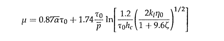
The coefficient of friction fed into LLTCA is determined with the values selected using the Evans-Johnson method:
Friction parameter ζ is:
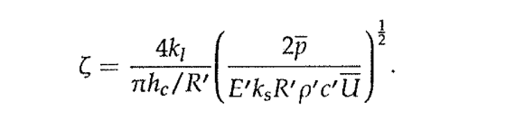
Eq 14
kl is the lubricant’s thermal conductivity,
ks contacting tooth flanks thermal conductivity,
α is the piezo viscosity coefficient at ambient temperature
p is the mean contact pressure
he is the contact film thickness,
t0 is the limiting characteristic shear stress,
ρ is the density of the lubricant
c’ is the specific heat derived from that of the lubricant film in contact with the solid contact of the tooth flank on the driver side and the tooth flank material itself, with its specific heat.
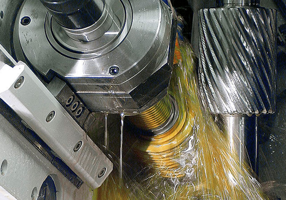
5. Friction Effect and Evaluation
When the loaded gear tooth flanks undergo higher pitch line velocities:
This method is used to ascertain the behaviour of the tooth flank surface under lubricant pressure and is often applied to estimate the heat transfer parameters. This phenomenon is taken into consideration in changes in tooth flank geometry due to thermal effects, especially on load in finish grinding.
Friction in the gear exists over the engaging tooth surface as relative sliding exists thereon, except at pitch points.
The following equation can describe the work of friction as an integral of the distribution of the friction factor.
qF = μ .parva
μ is the friction factor
Par is contact pressure
Va is the sliding velocity
qf is the particular amount of heat generated
As the oil film formed between tooth surfaces is supposed to carry away the heat generated by sliding velocity, it follows as yet this value may not be bigger at times, based on the operating conditions, mostly the rotational speed. This results in the heat getting conducted to the tooth flanks.
Besides, the lubricant mineral oil flows into the control volume at the end of the teeth, along the face width and causes losses due to windage.
The heat transfer coefficient between the lubricant medium and tooth flanks depends on the type of flow and relevant non-dimensional numbers – Reynolds, Prandtl, and Nusselt- based on the threshold value for flow.
The heat energy absorbed into the pinion and wheel need not be the same, and based on the dimensions, pitch line velocity, and diameter/length for conducting the temperatures gained by them would be unequal. It takes time for the momentary heat flux at the Hertzian contact width along the contact line of action.
The friction loss between a pair of engaging tooth L0 can be expressed as:
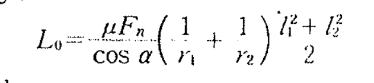
Eq 15
l1= length of line of action of pinion
l2 = length of the line of action of gearwheel
According to Japanese researchers, the friction loss estimate follows:
Eq 16
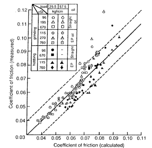
Fig 4
From equation 16, one can find that the precision on estimation of the mesh friction loss is important and the friction coefficient for the necessary pressure value.
The research on high-speed gears where V is greater than 120m/sec reveals that a relationship exists between the friction coefficient and a factor D under rolling and sliding conditions.
The friction ‘D’ value is the total maximum tooth surface roughness/ minimum oil film thickness.
The measured and calculated value of friction reveals that the force values are within a maximum error of 10%.
This follows that when D is less than 1, the friction coefficient is 0.01.
When D is between 1 and 10, the friction coefficient is
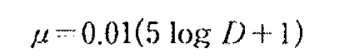
Eq 17
When D is greater than 10
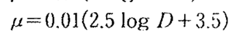
Eq 18
This estimate has been reported to give reliable values of the lubricated and loaded tooth flank behaviour under load and higher operating speeds
6. The method of approach for gears operating at larger rotational speeds and correspondingly higher power in evaluating the friction bears significance on account of the loss of mesh friction. The outlook of reduction or industrial drives there is a simplified method.
The measurement of friction losses in such drives consider the summation of tangential velocities of pinion and gear, sliding component of velocity, dynamic viscosity, of the lubricant which operates in EHL/mixed lubrication regime and finally reduced radius of curvature of contact flanks the sliding velocity is equal to the difference between tangential velocities of pinion and gear tooth flanks points at right angle to the line of action.
So the coefficient of local friction = 0.12
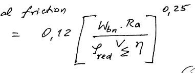
Eq 19
The normal load in unit length of contact Wbn, tooth flank surface roughness
Ra are among the deciding factors of load transmission, with friction acting on the flanks under a lubricant film frictions. The roughness factor is the mean value of the mean flank roughness values.
7. Under the analogy of hydrostatic friction, the following can be stated for relevance:
Although the total heat being the result of frictional loss along the contact line, it is calculated from sliding and rolling power loss components.
The value of the latter is smaller than that of the former in most gear applications; therefore, the total power loss can be computed considering only the sliding term.
Total power loss =
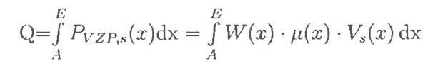
Eq 20
W(x) is the load distribution along the path of contact
μ(x) is the local friction coefficient.
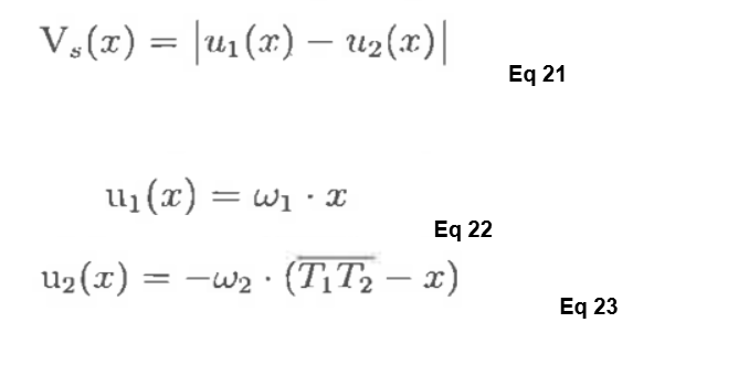
The instantaneous sliding speed is calculated from the rolling velocities of the pinion and gear at each mesh point on the line of action.
Due to the presence of sliding along the line of action, there is a difference in heat flux entering the gear tooth body. The heat partition is shown as:
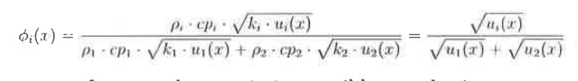
Eq 24
It is assumed that a partial EHL friction coefficient model for gears, where fluid friction μf is determined from the Eyring non-Newtonian equation. The reference stress is often calculated from the piezo viscosity coefficient, which avoids the characteristics of traction behaviour. The boundary friction coefficient μs is kept constant at about 0.7 for ground gears where the surface feed aligns with the axial direction.
The relationship is:
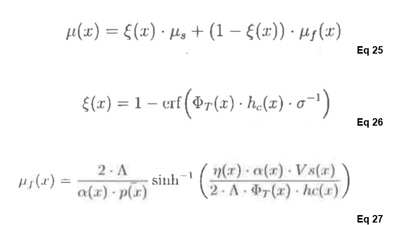
ζ(x) is the complementary side of the error function of rolling rolling-oriented loss of power mesh. This contains the heat transfer at point x, contact oil film thickness at point x. The heat loss factor through heat transfer is dependent on the entraining oil film speed at entry and is proportional to ζ(x).
The complementary term with hydrodynamic friction is responsible for the sliding loss of power in the mesh.
Λ is the limiting stress-pressure coefficient
δ is the RMS value of surface roughness of gear tooth flanks in mesh at an arbitrary point x.
Conclusion
In order to bring closer relationships between calculated and practically found values on the friction, it is important that the lubricant behaviour is taken into consideration. Assessment of various parameters of interest in design is required for evaluating reliability. The use of lubricated contact analysis is gaining importance. So the friction and the impact on assessment of losses, impact on running behaviour of gears and related operating conditions are the focus of research and interest. Failure prediction and understanding the mechanical forces rest on knowing friction performance well.
The paper addresses the area of a few friction factor assessment methods to suit the relevant applications.