In continuation to Part 1
2. Friction Coefficient Under EHL: When the operating parameters sustain the fluid flow under the action of load in the restricted area of contact between gear teeth, friction/ traction changes. The entraining velocity responsible for fluid flow into the contact zone and geometrical quantities like Slide Roll Ratio (SRR) are governing factors. This phenomenon on friction behaviour is better dealt by Swedish researchers, and a scenario is as follows:-
The ratio of difference in rolling velocities of meshing teeth and the mean of rolling velocities becomes the Slide Roll Ratio (SRR).
This parameter arising out of operating conditions, material of gear pair and position of line of action to the operating centre distance forms the component of relative Sliding to the rolling Component. This ratio is influenced by the design over the thermal effect generated by the loaded tooth.
In a way, friction loss as a part of power loss has its bearing on the friction coefficient estimation and applications. While the friction factor changes on account of contact surface roughness on tooth flanks, it is also a function of entraining speed to the SRR.
The friction charges linearly to SRR up to a certain level, assuming a steady entraining oil inflow and shear experienced over the film is not leading to changed shear rate.
The next phase is the non-linear friction coefficient over the same entrainment against an increasing SRR. This is attributed to the beginning of shear stress gaining a higher magnitude.
The third phase is similar to a plateau, with friction remaining uncharged during this phase where the non-Newtonian lubricant behaviour sets in.
The last phase of dropping friction is when the inlet temperature rises, and the flow becomes thermoviscous.
The EHD friction varying with SRR under the same loading and speed conditions may result in an error in the estimation of friction coefficients occurring in the Newtonian isothermal model.
When the shear thinning effect with the characteristics, shear stress reaching the limiting value the prediction of friction improve differently.
When the shear heating at the centre of conjunction gets added, the friction agrees with predicted & tested values at higher SRR values.
3. Friction is considered when estimating tooth friction losses as an important power loss; the same is calculated as:
Kelley’s method
Ploos = Pin Hv f
Where;
Ploss is teeth friction loss
Pin is the Input Power ( w )
The factory Hv=

β is the Hellix angle;
z1 z 2- pinion and wheel tooth number
Eq6
gf – length of approach path
ga– length of recess path (m)
pb+ Base Pitch
Here, the coefficient of friction is evaluated according to Kelley:-
Eq 7
p is the density ( kg/m3 )
v – oil viscosity ( Centistokes )
u- sum of rolling velocities (m/s)
Vg– Sliding velocity (m/s)
Fnu – Normal Tooth load per unit length of line of action.
Here, the friction changes per operating conditions on the path of contact.
An approximation is applied in finding the average of this friction coefficient along the path of contact.
4. Traction analysis:
To find which represents the actual situation of meshing gear tooth under speed and load, it is necessary to determine the lubrication regime for traction conditions. Usually, the Green Wood chart is used to determine this regime.
Often, the thin elastohydrodynamic films are formed as the gear teeth at higher loads and/or shear cause viscoelastic friction when the shear stress over the oil film exceeds the limiting Eyring shear of the lubricant. This value can subsequently reduce due to a rise in contact temperature.
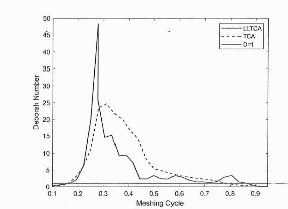
One method of ascertaining non-Newtonian viscous shear of the lubricant oil film is the use of the Deborah number.
This critical parameter is measured as:-
Eq 8
G a is the lubricant’s shear modulus, which can be related as:-
Eq 9
G= (G0+ α0p)
Where;
Go is the Shear Modulus at ambient pressure, and Bo is the thermoviscosity index. T and To are bulk and reference atmospheric temperatures, respectively.
Non-Newtonian viscoelastic traction is expected. When D>L
Shear stress and friction are brought up when the Lubricants behave in a Non-Newtonian manner
When Stress becomes:-
Eq 10
γ is the non-linear Shear rate;
n dynamic viscosity
F(λ) is the Havriliak–Negami Function
The above relationship is used to determine the actual shear stress under the condition of non-Newtonian behaviour of lubricant when the Deborah number D>1.
When it is otherwise, the shear stress is:-
Eq11
at Conventional Newtonian shear.
The condition of equation.10 occurs when the shear stress depends on pressure.
tl = Limiting shear stress =
When p̄ is the mean contact pressure
γ limiting shear strength proportionality Constant. –
This value is evaluated for the given lubricant and its properties for substituting the relevant data.
On account of Lubricated Loaded Tooth Content (LLTCA) mastering from the real tooth flock geometry. The Deborah number can charge during the mesh cycle on the basis of acted tooth profile deviation data. Where the load gets applied and influences the film thickness then and there, unlike the result, which can be different when lubricants free-contact are evaluated. Under LLTC, the Deborah number changes non-linearly over the generating length of the tooth mesh.