During our interactions with customers, we find that the common challenge faced by customers about getting incorrect component parameters using Corrected Lead Hobs.
The topic will address the following questions.
What is Corrected Lead Hob?
In Corrected Lead hobs, Module & Pressure Angle of Hob is different from that of the component. If the Pressure angle of hob is less, then it is a Short Lead Hob and when Pressure Angle is more, then it is Long Lead Hob.
Why is it necessary to design Corrected Lead Hob?
When the True Involute Form (TIF) diameter and Fillet Radius of the component are not achieved with the original Pressure Angle, then the Pressure Angle is reduced or increased to obtain the correct TIF & Fillet Radius. This can be explained with the following example.
Standard Hob Design: Our requirement is that TIF Shaving should be below required TIF Diameter. However, when hob is designed in a normal way, the TIF required & TIF shaving are almost at the same values as is visible from Picture 1.

Picture 1 (Generation with Standard Design)
Corrected Lead hob Design: We reduce the pressure angle of Hob from 20° to 18° and generate the component. As is evident from Picture 2 below, the required TIF diameter is above TIF shaving as per the requirement of the drawing.

Picture 2 (Generation with Corrected Design)
Hence, the corrected lead hobs are necessitated to be designed due to limitations in achieving the component data.
Machine Settings
Corrected lead design hobs bring new challenges at the time of setting on Hobbing Machines. With the various kinds of machines in operation like Manual, Semi-CNC & Fully CNC machines, hob settings in each type of machines differ.
Important Points to keep in mind while setting on the Hobbing Machine.
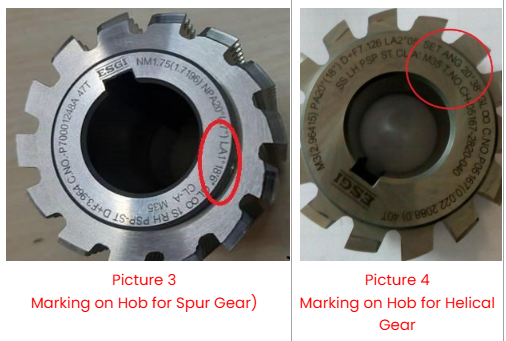
Spur Gears: Lead Angle is the same as Set Angle. Hence, only Lead Angle will be marked on the Hob. Please refer to Picture 3.
Helical Gears: Hob set Angle is different from Hob Lead Angle, and both angles are marked on Hob. Both the Lead Angle & Set Angle are marked on hob. But for setting on Machine, only Set Angle should be referred. Please refer Picture 4.
Manual Hobbing
Spur Gear: Hob Lead angle as marked on the Hob is to be manually set on the machine. For example, referring to picture 3, the value to be manually set on machine is 1˚18’06”.
Helical Gear: Hob Set Angle (Not Lead Angle) as marked on Hob to be manually set on the machine. For example, referring to picture 4, the value to be manually set on machine is 20˚38′.
Semi-CNC Hobbing Machines (where the Hob lead angle is to be set Manually)
The procedure to set up the Angle remains the same as in Manual Hobbing Machines. However, you will find two files for inputting the data, one for component data and another for Hob data.
Component Data File: Input Original Module & Original Pressure Angle
(Module 3 & Pressure Angle 20 as in Picture 2).
Hob Data File: Input Corrected Module & Corrected Pressure Angle
(Module 2.96415 & Pressure Angle18˚ as in Picture 2).
CNC Hobbing Machines (where Hob lead angle is calculated by the Machine)
In this Case, there is no need to input the Lead Angle or Set Angle. The operator must ensure to input the values in both the component & Hob file.
Component Data File: Input Original Module & Original Pressure Angle
(Module 3 & Pressure Angle 20˚ as in Picture 2)
Hob Data File: Input Corrected Module & Corrected Pressure Angle
(Module 2.96415 & Pressure Angle18˚ as in Picture 2)
However, the operator must ensure that the Hob Set Angle calculated by the machine is the same as marked on Hob.
Incorrect settings or feeding incorrect values will lead to wrong component parameters, like the Root diameter and profile.
Hope the above article will help in bringing clarity about the necessity to design, how to use Corrected Lead Hobs and understanding machine settings based on the type of gear and machine.
Please write to me at esgi@esgitools.com for any challenges in the usage or selection of Gear Cutting Tools.