Usually, in a typical gear hobbing machine, we observe that almost all common transmission components are used. Especially if we look into conventional machines, we find them all used to transmit the power to the movement of slides, the hob spindle, and the worktable.
In the conventional gear hobbing machine, all the interrelated movements are done through one single main motor and clutches are used in the mechanical kinematics to transmit the motion to the respective axes at a given time.
All gear hobbing machines, whether mechanical or CNC, consist of the following important characteristics listed below:
1. A work table to rotate the workpiece and the hob spindle to rotate the hob.
2. A mechanism to rotate the work table and cutter spindle with an exact ratio, depending on the number of teeth to be cut on the gear and the number of starts of the hob. In conventional hobbing machines, this ratio is obtained by a series of gears, commonly known as an Index gear train.
3. A mechanism to traverse the hob across the face of the workpiece. To cut helical gears, another series of gears was used to rotate the work spindle with an exact ratio related to the finite hob traverse in the axial direction, i.e., across the face width of the gear. This rotation, called differential motion, depends upon the helix angle to be generated on the gear tooth and the finite distance of the hob traverse. This gear train is known as differential gears.
4. A mechanism to adjust the centre distance between the hob and workpiece for making workpieces of different sizes.
CNC gear hobbing machine has direct drives for all axes, as well as work-spindle and cutter-spindle. Relation between the cutter-spindle and work-spindle are controlled through a CNC function called EGB (Electronic gearbox) which eliminates the need for index and differential gear mechanism. Separate and direct drives for every drive axis eliminate clutches. Following is the kinematic of a CNC Hobbing machine
In CNC hobbing machines quite obviously number of components are few as compared to the conventional thanks to the technological advancement in synchronous motors and drives. It has become possible to design and built machines with backlash free drives which are essential characteristics of gear cutting machine tools. It has also rendered the machines simpler for manufacturing and assembly.

The transmission components have stringent requirements in terms of quality. The heat-treated parts undergo finishing operations to meet the high standards of accuracy. Thus, they can meet the standards of reliability and durability and can expect functional characteristics in machine operation throughout the life of the machine tool.
The following could be typical Transmission components used in Gear Hobbing Machines
Index Shaft:
This splined shaft transmits power from the change gearbox to the worm which in turn drives the worm wheel. The worm and the worm wheel, which form the index drive, are housed below the work table.

Worm-Worm Wheel Drive for the Worktable:
The value of the hobbing machine depends to a large extent on the accuracy of its index worm drive. The qualities are directly transmitted to the gear hobbed. For this reason, the diameter of the index worm gear of the machine is made as large as possible, approximating the diameter of the work table.
In order to maintain high accuracy even after the machine has been in operation for many years, it is equipped with an adjustable dual lead worm. The centre distance always remains the same which also ensures that the accuracy of the machine will also remain very high for many years.
Spindle Drive for Hob Cutter
Usually in conventional machines MT or SK tapers are used for holding the hob arbor. These arbors are tightened in the spindles by mechanical clamping with a tie rod or the Belleville springs and unclamped mechanically or hydraulically. The power transmission to the spindle takes place through the gear pair – a pinion and the main gear – mounted with close tolerances to minimize the backlash to the lowest possible value.

Adjustment of hob speeds by means of V belt pulleys, and of feeds employing feed change gears. For a speed change, it is merely necessary to change the position of one belt. More extensive variations may require changing the belt pulleys.
Index Change Gears
Index change gears are used to develop the number of teeth required on gears. Primarily there are 4 sets of index gears which determine the number of teeth on the gear. Power from the index gear is transmitted through the index shaft to the worm of the table drive. The worm in turn drives the worm wheel and thus the work table obtains the rotation. An idler gear is used in case of reversal direction of the worktable rotation.

Differential Change Gears
These gears play an important role in transmitting power to the feed drive shaft for cutting helical gears. They transmit power to the feed drive shaft only when the additional motion is to be given to it. The feed drive shaft can be the trapezoidal screw or the ball screw. The additional motion depends on the hand of the helical gear. Similarly, like index change gears, the reversal of additional motion direction can be obtained by the use of the idler gear.
PIV Drive
In old-generation machines ‘Positively Infinitely Variable (PIV) Drive was commonly used for the cutter spindle. It facilitated the stepless drive without slipping within a certain range and thus the operator was able to adjust the hob speed as desired for the gear cutting.
Trapezoidal Screws
These screws were used for the axial slide i.e., hob slide. Its movement provided the feed in the axial direction used for cutting the gear.
Straight & Spiral Bevel Gears
Bevel gears are used in differential gear trains, which can transmit power to two axes at 90 degrees to each other and rotate at different speeds. While Spiral bevel gears are used for transmitting power to the hob spindle and the hob head swivel axis.
Transmission Components in CNC Gear Hobbing Machines
Servo Motors
The servo motor is a closed-loop mechanism that incorporates positional feedback in order to control the rotational or linear speed and position. The motor is controlled with an electric signal, either analogue or digital, which determines the amount of movement which represents the final command position for the shaft.
The position sensor provides a feedback signal corresponding to the present position of the axis. This sensor is normally a potentiometer that produces the voltage corresponding to the absolute angle of the motor shaft. A servo drive needs a command signal given to the motor to compare the real and desired position of the motor.
The function of the servo motor is to convert the control signal of the controller into the rotational angular displacement or angular velocity of the motor output shaft.
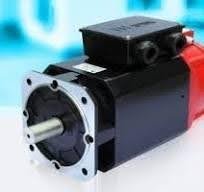
AC Spindle Motors
AC Spindle Motors are the powerhouses that drive the rotating spindle in machinery used for various precision operations. These motors are meticulously engineered to deliver high-speed, high-precision performance. They are a vital component in industries where precision and efficiency are paramount.
1. Unmatched Precision
AC Spindle Motors are engineered to offer the highest level of precision. Their ability to maintain consistent RPM, even under varying loads, ensures that the end product is finely crafted with no compromises.
2. Efficiency and Productivity
The efficiency of AC Spindle Motors is unmatched. They deliver power precisely when needed, leading to faster production cycles and reduced energy consumption, thereby increasing productivity.
3. Durability
These motors are built to last. With robust designs and the latest technology, AC Spindle Motors withstand the test of time, ensuring your investment is secure.
Timing Pulleys & Belts
Timing belts offer a broad range of innovative drivetrain solutions; these drives employ the positive engagement of two sets of meshing teeth. Hence, no slippage and almost no backlash, maintaining a constant speed ratio, all extremely important in any application and more so in automated machinery requiring indexing or sequencing.
Timing Pulleys come with many distinct advantages, such as…
Ball Screws
Ball screws are used to provide the precise linear motion required in machine tools.
The ball screw consists of a screw and nut with matching grooves and ball bearings that move between them. The unique element of ball screws is the ball bearings, which increase the power efficiency by minimizing the friction during the movement of the ball and nut.

Ball screws are generally better suited to applications that require smooth motion, efficiency, accuracy, precision and prolonged continuous or high-speed movement. Lead screws tend to be more suited to transfer applications where speed, accuracy, precision and rigidity are not as vital.
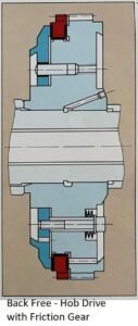
Backlash Free Hob Drive
Equipping the hob spindle drive bull gear with friction gear having one more tooth for zero backlash results in low relative motions between the drive members thus causing no thermal problems. The applied preload and the friction liner provide uniform tooth contact and a braking effect that prevents tooth flank lift-off even under heavily varying cutting forces.
The double index drive:
This mainly consists of double worm–worm wheel drive. Out of this one is the driving worm and the other is the brake worm. The brake worm is hydraulically loaded in the direction opposite to the rotation. Its hydraulic preload provides excellent stiffness and assures backlash-free as well as maintenance-free operation of the table drive.
Direct Drives / Torque Motors
Direct-drive motors have much higher torque than a standard servomotor and much lower speed.
KEY HIGHLIGHTS