Introduction
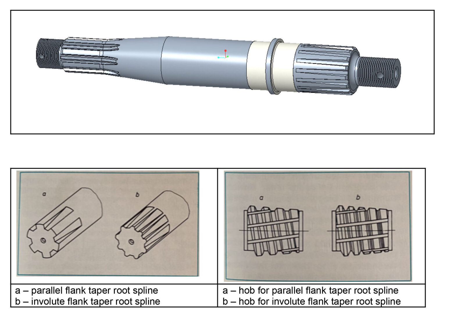
In many cases, it is desirable to secure gears which transmit large forces with a tight fit at the shaft ends. Both parallel spline shafts and involute spline shafts can be considered for this purpose.
Connections with tapered root spline shafts are being in use with this feature. These not only hold on the flat tooth flanks, but also in the conical bottom at the root between the flanks. These spline shafts, with such requirements, can be cut diagonally by conical hob cutters.
For hobbing of these shafts, special hob cutters are used whose outside diameter is tapered. The cutters have constant pitch
and tooth thickness.
Component

Sample component
The component has splines at one end. The splines have tapered root diameter but the top land and the gear teeth flanks are straight and run parallel to the component axis.
A photograph of the component as seen above gives a fairly good idea about the form of the gear tooth desired.
Gear Hobbing Machine
The machine must have a universal hob head with provision of compensating the tangential differential motion to the worktable rotation. This can be obtained through tangential differential change gears in conventional machines or through an Electronic Gearbox in CNC machines.
Gear Hob
In one of the examples in which we proved the diagonal hobbing, the hob developed had following unique characteristics:

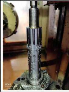
Setup on a Cooper P 254 hobbing machine
Workholding Fixture
The workholding fixture developed was simple. It had a carrier for clamping and driving the workpiece while cutting. The component was located between centers. A steady rest can be provided to the component to impart firm support, if required.
The main cutting block in the program must contain the end position coordinates for axial Z and tangential Y axes with their respective feed rates at a predetermined ratio.
Thus, there is simultaneous movement of hobs in tangential and axial direction with their proper feed rates.

Sample hob
Cutting Process
With the help of diagonal hobbing, the tapered outer contour of the hob cutter creates a tapered tooth base on the spline shaft.The cutting takes place in axial-tangential direction thereby
producing root taper by virtue of tapered hob teeth.
In this method of hobbing, axial and tangential feeds are used simultaneously for cutting the gear. The hob continues to shift and its entire length is used in every pass.

Therefore, the cutting process is called Diagonal hobbing as the hob traverses diagonally in feed in Y-Z plane along an interpolated path.
The hobbed taper gear by diagonal hobbing has taper root with both flanks parallel, and width of top land remains the same across the face width of the workpiece.
At the start, the large diameter of the hob cuts at the position where the tooth depth on the workpiece is maximum. From this position, the hob travels both axially and tangentially producing lesser tooth depths on the workpiece.
At any axial position of hobbing during diagonal feed the center distance between the hob and workpiece is constant.
Other characteristics of the cutting process used for trial are as under:
Following conditions apply to the movements of the axial slide and the tangential slide while cutting splines by diagonal hobbing method.
While the axial slide moves by the axial path lz, the tangential slide has to move by the tangential path lt.
In relation to a workpiece revolution, this means:
An axial feed Sz includes a very specific tangential feed St.
The following applies: Sz / St = lz / lt
There is an important point to note; when the hob leaves the workpiece, there must not be any digging mark or radius left
at the spline end. In fact, there should be a smooth merging of the teeth ending with the workpieces outside diameter
all around.
This can be achieved by giving exact coordinates of start position and end position. It can also be done by adjusting the tangential position of the hob by desynchronizing the coupling to change the contact section of the hob.
Advantages of Diagonal Hobbing
Better utilization of all teeth of hob takes place.
It is useful for cutting “taper root splines” by means of a conical hob.
It is used for cutting large face width of gears or large
diameter gears used in operating sluice gate of dams.
This diagonal hobbing process helps to achieve constant gear size across the face width.