Martin Witzsch
Transmissions for electric cars are much simpler in design than for conventional combustion engines, but place far higher demands on the manufacturing precision of the gears used. Thanks to completely new procedures for quality assurance directly in the final machining process, which is gear grinding, these specifications can also be met in series production.
All-electric vehicle drives usually make do with two-stage, non-shiftable transmissions. You would have thought that this would greatly simplify production. After all, this type of transmission design has just four gears, distributed between the drive shaft, the second stage with fixed gear and intermediate shaft, and the axle drive gear. But in reality, it’s not that simple: first of all, engine speeds are much higher for the e-drive than for combustion engines, at up to 16,000 rpm. This means electric motors deliver an almost constant torque over a wide speed range. Unlike combustion engines, it is applied to the transmission right from zero speed. Furthermore, there is an additional constraint that makes production much more demanding than with the conventional drive train, as Friedrich Wölfel, head of machine sales at Kapp Niles, describes: “The noise from a combustion engine masks the transmission noise, meaning it is not noticed in the first place. On the other hand, an electric motor is almost silent. Above about 80 km/h, rolling noise and wind noise are the predominant sounds, irrespective of the drivetrain. But below that speed, transmission noise can be irritating in electric vehicles. We also have to take that into account when manufacturing gears.”
Of course, the flank load capacity of the gears and good running properties are also of paramount importance with e-drives. However, the almost constant torque level and the high speeds require a different gearing design, which in turn can affect the noise dynamics. Here, in particular, demands are higher than with combustion engines.
However, when it comes to the pressure to generate maximum efficiency, there is no difference at all between gears for e-vehicles and conventional drives. Accordingly, the highly productive generating grinding process is also generally used as a fine machining process in the series production of e-transmission gears.
The challenge for Kapp Niles, as a specialist in the hard fine machining of gears, is to implement a generating grinding process that is both productive and, above all, optimised in terms of noise dynamics.
Achim Stegner, Head of Predevelopment at Kapp Niles, describes the basics: “Depending on the modifications of the gearing defined at design stage, such as line corrections, width convexity, head retraction, as well as the profile and line interlocks typical of the process, characteristic noises occur in the transmission during meshing, which can be assigned to specific tooth meshing frequencies. The entire transmission, in turn, also exhibits characteristic properties with regard to structure-borne noise and radiation, depending on the constructive design. This is stimulated in the tooth meshing frequency and its multiples. Manufacturers try to minimise this effect as much as possible by adapting the design of transmission and gears.”
For the time being, these considerations only apply to “perfect” gearing. But of course, like any other mechanical component, gears also generate variances from the ideal target geometry in series production. These have different causes and effects, as Achim Stegner explains: “In addition to the stimulation caused by the tooth mesh, there are other disturbance variables that can result in noises in the tooth mesh. These make themselves felt as ‘ghost frequencies’. These are frequencies that do not coincide with the tooth meshing frequencies and their multiples, and can just be introduced into the component during grinding.” Ghost frequencies are caused by minimal irregularities that are almost impossible to completely avoid in series production. It becomes particularly critical when these variances map almost exactly onto the circumference of a gear, as this results in harmonic stimulation. It takes a lot of expertise and process experience to recognise the reasons for such irregularities and, if possible, to avoid them in the first place.
The cause of such malfunctions can be found, for example, in the axis drives of the machine tool used. Electric motors have certain pendulum moments. Measuring systems work with discrete line counts and finite eccentricity errors from assembly. Last but not least, balance condition and spindle bearings can contribute to possible irregularities. Waviness as small as 0.1 mm can cause noise in gears. Achim Stegner explains some more causes: “Every machine has natural vibrations. For example, the typical natural frequency of a workpiece spindle is about 250 Hz. This can also be reproduced exactly on the workpiece if the speed constellation in the generating grinding process is unfavourable. We can eliminate such effects by the clever choice of a suitable speed window during machining.”
Once the optimisation potential on the machine side has been exhausted, there are also a number of technological options for improving component quality in terms of noise dynamics. These include, for example, the selection of the number of gears of the grinding worm, the speed ratio during dressing and grinding, the finishing speed and the feed rate.
Roughly speaking, there are two typical types of error patterns in serial gear grinding: on the one hand, trends are emerging that show a continuous change in characteristics. On the other hand, there are individually conspicuous components. Trends are usually easier to control. They can be caused, for example, by the gradual wear of a grinding worm. If permissible manufacturing tolerances are exceeded here, it is usually sufficient to shorten the cycle between two dressing processes. They can also be easily recognised during component testing by a gradual approach of the measured values to the tolerance limit.
Component-specific defects, on the other hand, are unpredictable. They become noticeable through sudden deviations in one or even several quality criteria. This can be caused by grinding worm chipping, workpiece blank errors or set-up errors.

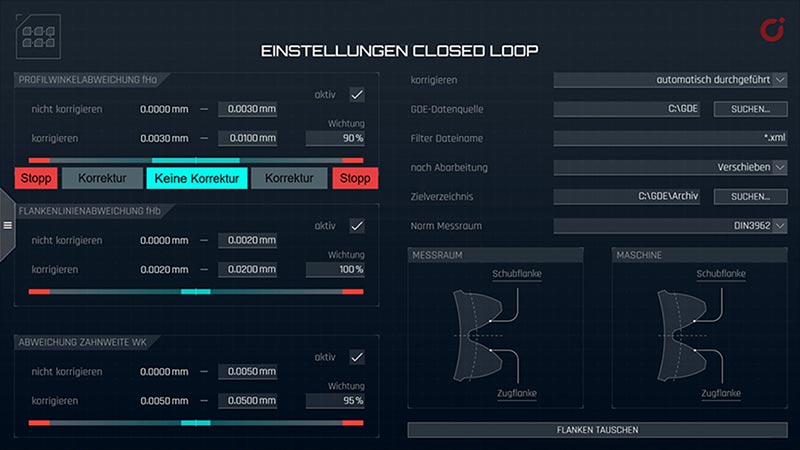
Figure 1: Tolerance corridors for closed loop
Since the actual machining of a gear takes much less time than the control measurement in highly efficient manufacturing processes such as generating grinding, it is also not possible to inspect every single component. In addition, as described at the beginning, quality demands for gears for e-transmissions are extremely high. “The required tolerances of profile angle, flank line angle, concentricity, two-ball dimension are in some cases smaller than in the conventional drive train by a factor of 3. For the flank line angle error fHß, a typical requirement is ± 4 mm; with combustion engine transmissions, this was sometimes ± 13 mm,” says Friedrich Wölfel, describing the requirements of his customers. Together with the required machine and process capabilities, these quality requirements are testing the limits of what is technically and economically feasible. And the static and dynamic stability of the processing machine and process cannot be increased at will. The only way out is to start with the methods of analysis and control. Because otherwise: the narrower the tolerance limits become with the same machine/process capability, the greater the number of measured components must be. However, this involves a great deal of effort. And ultimately, downstream component testing does not add value either.
With regard to the approach to trend-related deviations from the target geometry in particular, the ‘closed loop’ has already established itself as an important tool. This accelerates and improves the feedback between downstream gear measurement and the processing machine itself. Here, the results of the inspection on the measuring machine are no longer printed out and made available to the machine operator on paper for evaluation, but are transmitted directly to the processing machine as a standardised file. The grinding machine then uses preselectable tolerance corridors to decide independently whether it needs to intervene in the process at all, for example with scalable correction values. If unexpectedly high variances from the target geometry occur, the decision on how to proceed is then up to the operator themselves (Fig. 1).
A promising approach is indeed to detect possible defects as early as the grinding process. Process monitoring is the buzzword. Achim Stegner explains the approach: “We already have numerous sensors and measuring systems in the machine that can provide us with many indications, measured values and information. At the moment, we primarily use it only to operate the functions of the machine. In the future, however, we also want to use it to assess the machining process directly in the machine.”

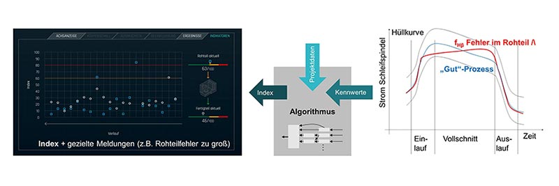
Figure 2: Error analysis and index calculation in the machining process
However, this does not mean integrating an additional tactile measuring function into the grinding machine in order to achieve a faster closed loop. Nor is it a question here of inspecting a ground component directly in the machine, evaluating it and correcting any discrepancies during the production of further components. The focus is rather on analysing the machining process in real time (!) in order to detect deviations from a previously defined reference process. However, it is not enough to only define envelopes for signals from the machine to do this. This can be explained using the “power consumption of the grinding spindle” signal in Fig. 2 as an example. This signal can be used to detect a possible flank line angle error (fHß) at an early stage. Stegner: “However, the procedure via envelope detection reaches its limits here, as the error is difficult to identify. As long as the signal remains within the envelope, no alarm gets triggered. So you need a more intelligent form of evaluation. An artificial intelligence that attempts to emulate human decision-making structures. This involves making decisions based on a multitude of different information – overlaid with the person’s own experiences – upon which they act.

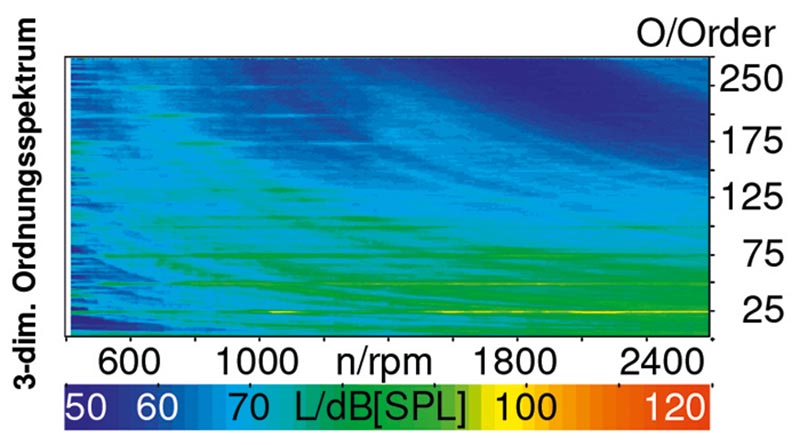
Figure 3: Order spectrum, recorded on a transmission test bench
Process monitoring can be defined as component-specific monitoring and evaluation of the grinding process. As described, it is not a trivial matter to generate an action instruction from the sensor signals. But it is possible. Various characteristic values can be formed from time signals. In the simplest case, these can be maximum or RMS (Root Mean Square) values of the signals. The characteristic values are then combined with the known project data via algorithms and processed into indices, for example a noise or screw breakout index. Achim Stegner explains about the transmission noises specifically: “An order analysis similar to the order spectrum on an end-of-line test rig can be created for noise-critical components via an FFT (Fast Fourier Transformation). This makes it easier to classify the recorded signals and relate them to results on the transmission test bench (see Fig. 3). Measurement data that is not processed is of no use.” In the end, especially in the manufacturing environment, only appropriate indices help to identify errors very specifically. The benefits of process monitoring can therefore be seen in the following points:
Process monitoring is not yet an app that you can simply download and use. Rather, it is a customer- and application-specific development that defines and monitors indices in relation to the respective component. But even this first step is far more than was considered feasible until only recently. Achim Stegner on this: “Several pilot customers are already using this functionality today. We are already able to detect different errors and intervene on the process side. In addition, we are already working on having the grinding machine teach itself characteristic values for new components. However, this of course requires broad empirical knowledge from error patterns, the geometric quality of the components and corresponding feedback from the transmission test bench.” Friedrich Wölfel adds:
“The next goal is that the user can also use this functionality without our component-specific support. It is also important to understand that process monitoring and closed loop are not contradictory, but complementary.”
Both approaches to process-integrated quality assurance are already available for Kapp Niles machines today and are continuously being given further functional scopes and utilisation options through the experience gained from series production.
Author
Graduate physicist Martin Witzsch, freelance journalist on behalf of KAPP NILES
Contact
KAPP NILES GmbH & Co. KG
Tel.: +49 (0)9561 / 866-0
info@kapp-niles.com
www.kapp-niles.com
Martin Witzsch, freelance journalist
Haßfurter Straße 20, 91056 Erlangen
Tel.: 09131 / 9266725
info@witzsch.com