By KP Soundarajan
An efficient and reliable transmission of power involves the interaction of forces which are transmitted by a carefully developed set of components. These components must withstand various complex stresses produced by the forces involved. Gear teeth transmit loads through a process of sliding, rolling, and negative sliding of contacting surfaces.
The contact is responsible for the development of bending stresses at the root of the gear tooth and contact stresses at flanks. These are basic yet important life aspects of loaded gears which are of case-hardened ones.
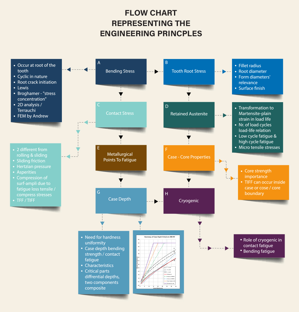
By calling the fatigue properties of such gears, the influencing features are many that contribute to fatigue. With the help of a simple diagram, these are shown in blocks in serialising order of A, B, C, D, E, F, G and H. Each of these blocks contain the respective engineering principles or facts.
The gear teeth transmit load/s through a complex process of positive sliding, rolling, and negative sliding of contact surfaces. This is the cause of development of bending stresses at the root and contact stresses in the meshing involute flanks.
Here, we look at each block individually.
These occur at the root of the tooth due to transfer of load from one gear to the other.
The bending stresses are cyclic by nature which can lead to crack i.e., fatigue crack initiation at the root. This zone itself is a stress concentrator and the fatigue cracks are fractures in their position and role when these undergo alternating load peaks.
As everyone knows, per the Lewis calculation of stress developed in the root and his approach to the model, it is a notched beam in bending approximating to a parabola. It is fundamentally right even today, and gear geometry calculation and bending load still begin the understanding from here.
The stress concentrators were brought out by detailed explanation by researchers Broghamer and Dolan. The calculation of stresses was done in 2D analysis later by Aida and Terrauchi. These put together gave a good understanding of the importance of the tooth root stress. Around 2,000 Andrews came up with finite element analysis.
The bending fatigue is governed by gear geometry, the loading magnitude and material characteristics. So, elements like the parameter module have been connected to the endurance of the material to the bending strength to fix the module in accordance with the famous Maag approach.
Many descriptions have been known and read as well as practised more often with gear geometry, but more precisely the metallurgical factors are to be correlated too.
The interference zone contains the fillet where the true or modified form of active profile blends with the root region. The quality, the magnitude and finish in the fillet blend is a key area for stress concentration. The unfavourable intensity here is directly connected to the fatigue performance.
The radius is limited by any formation of undercut as a function of pressure angle and nr of teeth, root thickness ratio (this is termed as kf from the X factor), the hob or the gear cutting tool edge radius to form the fillet corner and the proportion of whole depth based on finishing.
The fillet formed by the generating rack or hob or tool is a trochoid, and should blend at either end smoothly. In gear cutting like hobbing, it is often guided to look for chip thickness size from the knowledge/ program and employ feed rate; the corresponding finish in the fillet area contributes to the stress after hardening.
The root diameter and the fillet radius are together the parameters for bending root stress effect in a fatigue performance evaluation.
The form diameter at the root region gets its position and relevance depending on where and how effectively the active profile for use begins. The tool geometry is calculated for the form diameters values and position with regard to the fillet. In short, the interference zone is very sensitive in values and finishes for fatigue performance.
The ‘tooth root chord’ in critical section (sfn) and a quantity stress correction factor Ys are load capacity based geometrical values which contain the fillet radius as their influencing factor.
Consequently, say for low cycle fatigue (where the uniform loading in the line of action) of case-hardened gear steel takes 3× 10^6 as reference to segregate those with higher nr of load cycles or lower to enable fix on life factor become interlinked.
For higher order load cycles, linear elastic finite element comes up to evaluate the fatigue effect from the nr of stress cycles.
More often the surface finish in the profile zone in pre-finishing and finishing are different on account of axial feed employed and the limitation of true involute portion to finishing leaving the pre-cut root region untouched. So, the favourable performance and fatigue life on this count depends on how the fillet area has been dealt in pre-cut. Shaving or hardening, grinding or hard skiving or honing, all face the above situation with regard to ‘the fillet region pre-cutting situation’ towards fatigue life.
These are out of loaded flanks experiencing the Hertzian pressures and the induced elastic deformation and some plastic zones based on the type of load, the surface heat production by friction, the component of sliding speed, and the summation of rolling velocities between the pinion and the gear.
The friction is a combination of both mechanical and hydrostatic friction, and depends on the heat flux created, the thermal conductivity of the surfaces, the micro depth of affected place all to add to the under substrate — stress values to indicate the fatigue.
By 3D mapping of slip as percentage, a principle analogous to slide roll ratio, entrainment speed for lubrication oil and the friction coefficient, it indicates the interlinked phenomenon of the three parameters on stress progression in the contact zone.
The plastic zones can be recognised through the film thickness and load equations, and can be in the order of a few microns in micro asperities contact.
There can be two plastic regions by continuous change of sliding and rolling due to different phenomena. The first one is a flank surface layer due to macro contact. The second one is due to micro asperities contact as mentioned above.
The depth of stress intensifying can be within about 50 microns where the surface roughness of the tooth flank plays a role on account of difference of entrainment velocity and asperities contact velocity. So, we can say that the friction has a role on the contact length.
The type of lubrication determines the film thickness in the zone of contact length.
The contact along the helix in helical gears with an overlap ratio of ebeta greater than 1 and transverse contact ratio of ealpha less than equal to 2 roughly ends up with the length of all contact oblique lines to ealpha times the face width.
Just a calculation of load along the face to see the influence of the load trapezium inclined to helical elastic yield. The above is a related but additional point of view.
The ratio of the surface asperities speed to the mean rolling speed in the continuous run impacts the oil film entry and compression of surface amplitude to affect the film thickness fluctuation.
This is complex due to the EHL phenomenon; the resultant heat flux gets to the surface or below based on friction factor. What was found with popular case hardening alloy steels is that a coefficient greater than 0.3 can bring the fatigue fracture in course of time at the surface.
A new analysis in gear grinding is monitoring and managing the grinding parameters to restrict the heat development in contact depth zone in case depth; this can cause additional heat burn thermal stress.
A ‘mechanism by which austenitic structure’ of case hardening steel during heat treatment when raised up to this elevated temp range based on carbon and quenching after a while to form martensite has been dealt in the tech literature.
So, we do not go to the type of alloying elements responsible for retention of austenite on cooling and how carbon has the larger effect and so on; similarly, the iron carbon equilibrium, temperature, time and transformation is ignored.
Researchers like Krauss, Zaccone, and those who measured the volumetric expansions and transformed micro structures/ properties to retain austenite etc., have shown the inter relationship between the fatigue performance and the retention of austenite.
In terms of austenite – the martensite transformation at the tip of a proceeding crack shows how beneficial it is to fatigue resistance and its mechanism.
Large amounts of retained austenite are accepted in terms of low cycle fatigue where the ‘plastic strains’ induce strain-hardening from austenite to martensite and the development of favourable residual stresses.
The plastic strain needed to transform is directly proportional to prior-austenitic grain size and size or morphology of austenitic packets before transformation.
In high cycle fatigue, the relatively low plastic strain does not quickly allow the transformation. The magnitude of such strain depends to a great extent on the fine grain structure. These structures will be able to transform the low amounts of strain into martensite, hence it can resist the crack progression.
There are several aspects in each of these mechanisms, and as mentioned earlier, the linear elastic finite element model helps to know better.
In a way, my learning is limited in progressive developments in this area but know that no systematic evidence has been out there with regards to outlining the nature, magnitude and micro stresses etc., on different case hardening steels and alloys as each is specific.
For example, sufficient details have been made available in some hot hardness steels with many alloys (like 9310 steel or AMS 6365) on their performance especially at elevated operating temperature fatigue failure tests based on research at Illinois Institute of Technology in the late 90s and early 2000s.
With this, we can look for E in some metallurgical influencing factors alone without going much into crystallography or metallography.
These factors depend on the composition of material used and its heat treatment. Additionally on their post heat treatment transformation in service is the structure change as said earlier by load impacted plastic strain.
The residual stresses and the effect of residual stresses and quasi stationary stresses change based on the surface load of the tooth flanks.
Loads on both flanks as in the case of reverse idler and torque at that speed are tackled by coarser pitch and longer face width.
Some designs consider residual stress induction in grinding the teeth through the final process using a non-dressable CBN grinding wheel to induce tangential compressive stresses in the substrate up to 20 to 30 microns.
These stresses increase the load carrying capacity on the flanks. They are measurable by X-ray diffraction using the Sin^2 phi method. Yet these stresses sit closer to the tooth flank surface in the substrate but not deep.
This was brought out by Prof Yokagawa in 1992 in a power transmission and gearing conference as an effect of CBN grinding. There are companies in the gearing field that carry on this technical phenomenon in the late ‘90s.
A corollary of this is at heavy commercial vehicle transmission- gear grinding in generating grinding process with an option of profile grinding and indexing for reverse idler.
There are German solutions that employ a cluster of these spur gears in an arbor type exchangeable fixture into a fixture base body with collet type clamping on a profile grinder.
Some of the other metallurgical factors are oxidation, decarburization, super carburization, carbide formation, grain boundary segregation, type and size or density of inclusions present, micro crack formation along with residual stresses which affect the fatigue performance significantly.
The core strength is of significant importance in fatigue resistance. This is because core strength has a direct impact on residual stress. The differential volume expansion between the case and core is responsible for the magnitude and polarity of the residual stresses developed.
When the difference is big enough, so is the residual stress. The carburized structure is a two-component composite and each has different elastic and plasticity properties.
When the stress levels are below the material yield point in both case and core, no significant overall stress state difference from the expected homogeneity. However, when load increases and the stress levels go beyond the yield stress, the core can behave plastically while the case still is elastic.
Due to different Poisson’s ratio for elastic behaviour the contracting tendencies vary; so transverse stresses are created in the interface region. This is the tensile bi-axial stress state.
The development of compressive transverse stresses lead to the higher ductility of the carburized part which helps to resist the applied stress. The presence of any inclusion in the case affects the case core transit plane and creates tooth internal fracture under fatigue.
The improved ductility of the carburized component compared to through hardened parts is by the development of compressive transverse stresses in the case. Volumetric expansion on transforming to martensite when straining can reduce the bi-axiality of the stress condition in the case.
A deep case may be seen to increase the degree of bi-axiality in the case-core interface while it restricts the ductility of the case. Some research in recent times has found that the nickel-chrome-molybdenum case hardening steel performs better than a normal 20MnCr5 type.
Case depth selected on the basis of contact fatigue perhaps may not necessarily perform at optimum for bending; at the same time, maximising for bending fatigue is usually overshadowed by the need for contact resistance.
To an extent, it can be said that even dual case depth is done in critically loaded parts for optimum fatigue strength in special gearing.
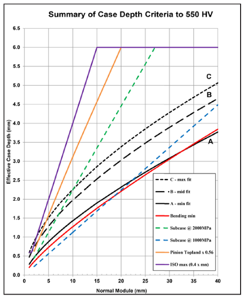
To influence the macro geometry in terms of optimum case hardening depth (up to a target hardness level), the formula used per standards gets split between that for contact zone alone or a maximum when both bending and contact stress are together considered by suitably changing the numerical factor in the formulae.
These can be seen in the enclosure along the bottom and top sides of the graph below where the module is in X axis and case depth on the ordinate. This is fine for TFF (Tooth Fatigue Fracture) as well.
There is a phenomenon WEA (White Etching Area) where the material structure is exposed to strong hydrodynamic pressure and sheer stress at the same time.
The origin of WEA beneath the surface results due to the presence of a mechanically thermodynamic state induced – high tensions where the sheer resistance of the material is exceeded.
The crack initiation can run in the direction of the greatest sheer stress where the flanks are heated in a short time.
In the process, carbides dissolve and carbon enters the gamma matrix. After cooling by itself there can be an oversaturated martensite due to the surrounding structures at relatively lower temperatures.
This is not an essential process for all case-hardened gears but applicable where the stress limits even the thermal of operating gears are at unfavourable environments; maybe at an altitude where the oil viscosity or the fluid flow inside a loaded heavy planetary gear undergoes a momentum ratio in penetrating the air medium to strike the tooth surface for lubrication; that results in an unfavourable Weber cross flow number.
Besides, the air density in such an environment would be sub atmospheric condition while the temperature matches with the typical operating value of the gear box system.
When the ratio of the pitch line velocity to the oil jet velocity changes to an unfavourable one, the gears have to “sustain their structure and overall stresses including heat energy to the target level in design in a time bound level before fracture.” Such gears also are those that require special treatment.
The effect of cryogenic treatment with respect to deduction of retained austenite, and if the belief of retained austenite can be there for transforming on straining, the overall applicability of cryogenics can have multiple but opposing views as well.
So, the necessity of its use has to be tested for specific conditions of material rather than a common statement.
Generally, the reduction of retained austenite for better fatigue properties and fracture toughness of the carburized parts due to development of residual tensile micro stresses require the process “cryogenic” as an essential practice.
In both the described conditions, the cryogenic treatment helps by adopting the gears to sub-zero temperature by suitable medium, mostly liquid nitrogen, it is practised where the “bending and contact fatigue properties” are to be sustained at adverse conditions of operation.
While the fresh tensile micro stresses induced are seen to be active for the purpose, there are opinions from certain users that these stresses are not favourable in the remaining austenite region.
Therefore, there are some applications where cryogenically treated gears showed a decreased fatigue performance in both bending and surface fatigues when tested. But by changing the base steel or compositions and cryogenizing in aerospace parts have been shown.
Conclusion
We can summarize the steps from A to H to briefly describe the main aspects of fatigue performance of case hardened (including ground gears) in service. Areas of material composites, design of gears and the best engineering practices contribute to better S-N properties for longer survival.
“Fatigue Aspects of Case-Hardened Gears” by G.P. Cavallaro, 1995
“White Etching Areas on Case Hardened Gears” by Prof Dr. Hans Winter and Dr. Gerhard Knauer, Technical University of Munich, 1989
“Proceeding of Institution of Mechanical Engineers”, Part G, 1989, Davies
 The author is former Director and General Manager of Gleason Works India. He has four decades of experience in the gear industry, with special reference to machine tools and gear processes. He is also a Fellow of the Institution of Mechanical Engineers, UK, and a registered chartered engineer.