Fig 3: tool system for chamfering on a standalone machine
Chamfering and deburring gears by machining processes is increasingly being considered by gear manufacturers. The decision to use machining processes for chamfering and deburring gears in mass production is mainly driven by their qualitative and economic advantages. After all, approximately three to ten percent of production costs are required for deburring processes.
There has been a lot of research on the issue of burr on gears being generated during the machining process. One strategy has been the investigation of burr formation mechanisms to minimize burr by setting the parameters of the machining processes properly.
Another strategy has been to modify the design of the cutting tools. For example, a sharp edge of the cutting tool with a small edge radius reduces the burr size. On the other hand, a sharp edge radius reduces tool life and tool life also plays a key role in terms of production costs.
There are a variety of methods that can be used for deburring or chamfering gears. Each of these processes has its limits, advantages, and disadvantages.
For example, a well-known technology for deburring is brushing, which allows you to round the edges of the gear. However, it is not feasible to produce a geometrically defined chamfer by brushing whereas the machining processes do not have such a disadvantage.
The ChamferCut technology is an established approach to deburr and chamfer gears economically. The resulting geometry of the chamfer is highly reproducible and well-defined.
This article explains the conventional ChamferCut process and introduces two new ChamferCut processes. The first ChamferCut process deals with chamfering geared workpieces with an interference contour. The second one allows chamfering of internal gears.
Figure 1 shows the principle of the patented ChamferCut process. The ChamferCut process does not differ significantly from conventional gear cutting with a hob. This process can be performed on hobbing machines or machines with the option to perform hobbing processes.
Both ChamferCut and workpiece have to be mounted on rotary spindles. The rotation of these spindles is coupled during the cutting process.
Further, the ChamferCut has a radial feed and is cutting skewed to the gear axis. The ChamferCut has to be set to an exactly calculated starting position.
As shown in figure 1 (A), this starting position is defined by the center distance (As), the distance from the tool axis to the workpiece (h) and the pivoting angle (eta).

Fig 1: Principle of the ChamferCut process
The profile of the ChamferCut is geometrically bound to the tooth gap profile of the gear. Both flanks and the root of the tooth gap profile can be chamfered at the same time.
The resulting chamfer has a constant chamfer depth (FV) normal to the transverse section of the gear as shown in figure 1. The number of the teeth of a ChamferCut equals the number of starts and is calculated by evaluating both setting and process parameters.
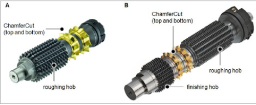
Fig 2: Examples of ChamferCut tool systems
Figure 2 shows examples for ChamferCut systems which can be used for chamfering gears or geared workpieces. The shape of the hobs can be designed as both a shank or bore hob.
These systems can be mounted into hobbing machines. Hobbing and chamfering a workpiece is done in different positions.
The process starts with standard hobbing. Afterwards, the ChamferCut tool system is set to another position in order to chamfer the top side of the geared workpiece.
This is done by considering the calculated setting parameters of the ChamferCut process. The bottom side of the gear is chamfered in a last step. Optionally, it is possible to finish the geared workpiece with a finishing hob (figure 2).
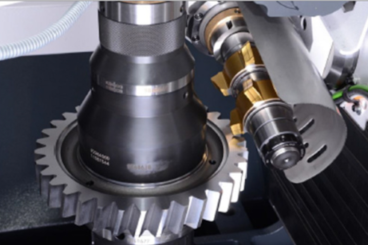
An additional tool concept to use the ChamferCut is shown in figure 3.
It is possible to perform the ChamferCut process on a standalone machine or on hobbing machines with an integrated ChamferCut unit.
This has the main advantage that the ChamferCut process can be performed during the main time of the hobbing process.
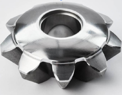
Fig 4: Bevel gear with chamfer produced using the ChamferCut process
In the ChamferCut process, the chipping volume is low which leads to a very long tool life. After a specific amount of chamfered workpieces, the ChamferCut has to be sharpened. The sharpening process is similar to the sharpening process of a conventional hob. A ChamferCut can be sharpened up to 20 times depending on the tooth height and the width of the wear marks.
The ChamferCut process allows chamfering a variety of gears or geared workpieces. It is possible to bring defined chamfers on straight or helical gears. For example, worm gears or bevel gears can be chamfered, too.
Figure 4 shows a bevel gear which has been chamfered with a ChamferCut. Although the edge of the tooth gap is a 3D contour, it is possible to use the ChamferCut process to manufacture a well-defined chamfer.
Geometry of the Chamfer
The geometry of the chamfer is designed by considering the chamfer quality, symmetry of the resulting chamfer. The resulting chamfer has a variable chamfer angle (CA) and a variable chamfer width (CW).
These are the pivoting angle (eta), the center distance (As) and the distance from the tool axis to the workpiece (h). This is illustrated in figure 5 using the example of the pivoting angle (eta) and the distance from the tool axis to the workpiece (h).
For example, a modification of the pivoting angle (eta) without changing the distance from the tool axis to the workpiece (h) leads to an asymmetric chamfer as shown in figure 5 (B). Further, there are critical values for the chamfer width (CW) and the chamfer angle (CA). The chamfer width (CW) and the chamfer angle (CA) may not fall below a certain limit.
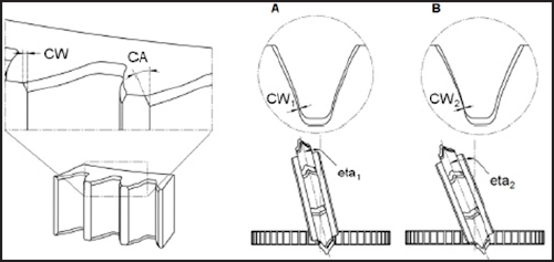
Fig 5: Influence of the setting parameters on the chamfer width (CW)
Figure 6 (A) shows an example of a gear with an interference contour. The tool path of the conventional ChamferCut would collide with the shank of the gear. The idea may be to increase the pivoting angle (eta) and decrease the distance from the tool axis to the workpiece (h) to avoid collision. As explained in the previous section, in some cases this is not possible. The chamfer width (CW) and the chamfer angle (CA) could fall below a certain limit and the quality of the chamfer would not be sufficient.
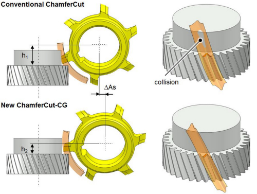
Fig 6: Conventional ChamferCut which would collide with the interference contour (A) and the new ChamferCut-CG with changed setting parameters which does not collide (B)
The solution for this challenge requires a change of boundary conditions.
If the flanks of the tooth gap are chamfered separately with two ChamferCuts, it is possible to change the setting parameters while maintaining a sufficient chamfer width (CW) and an adequate chamfer angle (CA).
A tool system for this new ChamferCut process is shown in figure 7. ChamferCuts, which are cut one-sided to avoid collisions, are called ChamferCut-CG (CG: Collision Gear).
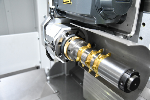
Fig 7: Conventional ChamferCut which would collide with the interference contour (A) and the new ChamferCut-CG with changed setting parameters which does not collide (B)
Further, with this new boundary condition it is possible to manufacture chamfers with a constant angle (CA). Within certain limits, it is even possible to generate chamfers with a constant chamfer depth (FV) and a constant chamfer angle (CA). Figure 8 shows an example of a gear with interference contour which is chamfered with a ChamferCut-CG system.
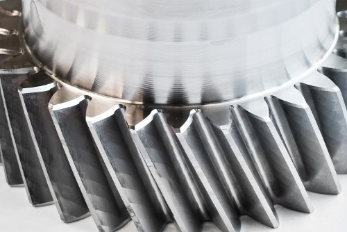
Fig 8: Examples for gears which are manufactured with the new ChamferCut process
Until now the usage of the ChamferCut process was limited to external gears. Hence, the mathematical model for the ChamferCut process has been extended. A change of both the setting and the process parameters allows the design of ChamferCuts for deburring and chamfering internal gears.
Chamfering gears are considered more by gear manufacturers to reduce production costs as it can be used for producing gears with a well-defined high quality chamfer. The ChamferCut-CG helps them use the ChamferCut process for gears with an interference contour. It is possible to design the chamfer geometry within certain limits. In future, the chamfer might be used as a design element, too.